
Dry floor heating system

A floor heating and dry-type technology, applied in hot water central heating systems, heating systems, heating methods, etc., can solve the problems of wet floor heating maintenance difficulties, uneven heat conduction, and high floor space, so as to improve the heating effect and increase the temperature The effect of shortening the time and high thermal conductivity

Active Publication Date: 2018-04-06
江苏唐盾材料科技有限公司
View PDF9 Cites 0 Cited by
  • Summary
  • Abstract
  • Description
  • Claims
  • Application Information

AI Technical Summary

Problems solved by technology

Traditional wet floor heating first lays a layer of insulation on the original cement floor, then lays heating pipes on top of the insulation layer, then uses concrete to backfill the heating pipes, and finally installs floors or tiles on top of the concrete backfill layer. The material, plus the ground decoration layer, is generally 8 cm high, which accounts for too much floor height; this kind of wet floor heating is difficult to maintain, it is laid with cement mortar, and the temperature rises slowly after heating; the heat conduction is uneven; the pH value is around 8, and alkali reversion occurs Up to 12 to 13; traditional wet floor heating structure due to the impact of concrete floor anti-alkali and uneven heat conduction, the applicable floor finishing materials are limited

Method used


Image

  • Dry floor heating system
  • Dry floor heating system
  • Dry floor heating system

Examples


Embodiment Construction

[0026] The present invention will be further described in detail below with reference to the accompanying drawings and specific embodiments.

[0027] The “horizontal” and “longitudinal” mentioned in this application are only used to cooperate with the content disclosed in the specification, so as to be understood and read by those who are familiar with the technology, and are not used to limit the conditions for the implementation of the present invention, so they are not technically The substantive meaning of the invention, the change or adjustment of its relative relationship, if there is no substantial change in the technical content, should also be regarded as the scope of the present invention.

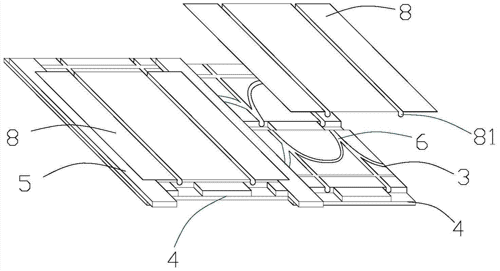
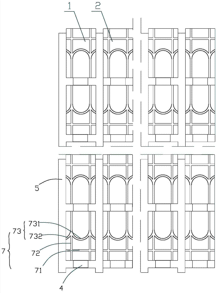
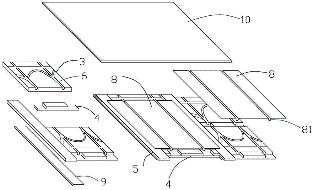
[0028] like Figure 1-4 As shown, the dry floor heating system of the present invention includes a first unit 1 and a second unit 2 . The first unit 1 includes two heat-insulating extruded plastic boards 3 with the same shape, two transverse reinforcement pieces 4 and two longit...


PUM


Abstract

The invention relates to the field of floor heating manufacturing, in particular to a novel dry type floor heating system. The system comprises a first unit and a second unit. The second unit comprises two heat preservation extruded sheets and two transverse reinforcing pieces. The heat preservation extruded sheets and the transverse reinforcing pieces are evenly distributed at intervals. The first unit comprises two heat preservation extruded sheets and two transverse reinforcing pieces and additionally comprises two longitudinal fixing pieces relative to the second unit. The longitudinal fixing pieces are installed on the two sides in the longitudinal direction, perpendicular to the transverse reinforcing pieces, of the heat preservation extruded sheets. The first unit and the second unit are arranged in a spaced mode. The transverse reinforcing pieces on the first unit and the transverse reinforcing pieces on the second unit are on the same straight line, and the portion, combined with the wall edge, of the second unit is provided with a trimming keel playing a reinforcing role. Grooves where water pipes are embedded are formed in the heat preservation extruded sheets, and the transverse reinforcing pieces and the longitudinal reinforcing pieces are provided with holes through which the water pipes pass; a heat storage panel is arranged above the heat preservation extruded sheets. According to the novel dry type floor heating system, the overall thickness is small, the supporting force is large, the module structure is convenient to maintain, and various facing materials can be used on the floor heating system.

Description

technical field [0001] The invention relates to the technical field of floor heating manufacturing, in particular to a dry floor heating system. Background technique [0002] Floor heating is the abbreviation of radiant floor heating. It uses the entire ground as a radiator, and uniformly heats the entire ground through the heat medium in the radiant layer of the floor, and conducts conduction from bottom to top using the ground's own heat storage and upward heat radiation. heating purpose. Compared with traditional heating methods, floor heating is more in line with the law of heat conduction, more conducive to appearance, more scientific and more energy-saving. [0003] In terms of heat medium, it is divided into two categories: water floor heating and electric floor heating. Water floor heating refers to a heating method that heats water to a certain temperature and transports it to the water pipe cooling network under the floor to achieve heating through floor heating. ...

Claims


Application Information

Patent Timeline
Patent Type & Authority Patents(China)
IPC IPC(8): F24D3/16F24D19/00
Inventor 沃成昌
Owner 江苏唐盾材料科技有限公司
Learn More