Cooling device for automobile part
A technology for auto parts and cooling devices, which is applied in the direction of fixed conduit components, heat exchanger types, lighting and heating equipment, etc., can solve the problems of increasing production costs, achieve increased cooling efficiency, compact overall structure, and space occupation The effect of rate reduction
- Summary
- Abstract
- Description
- Claims
- Application Information
AI Technical Summary
Problems solved by technology
Method used
Image

Examples
Embodiment 1
[0013] Embodiment 1 is basically as follows:
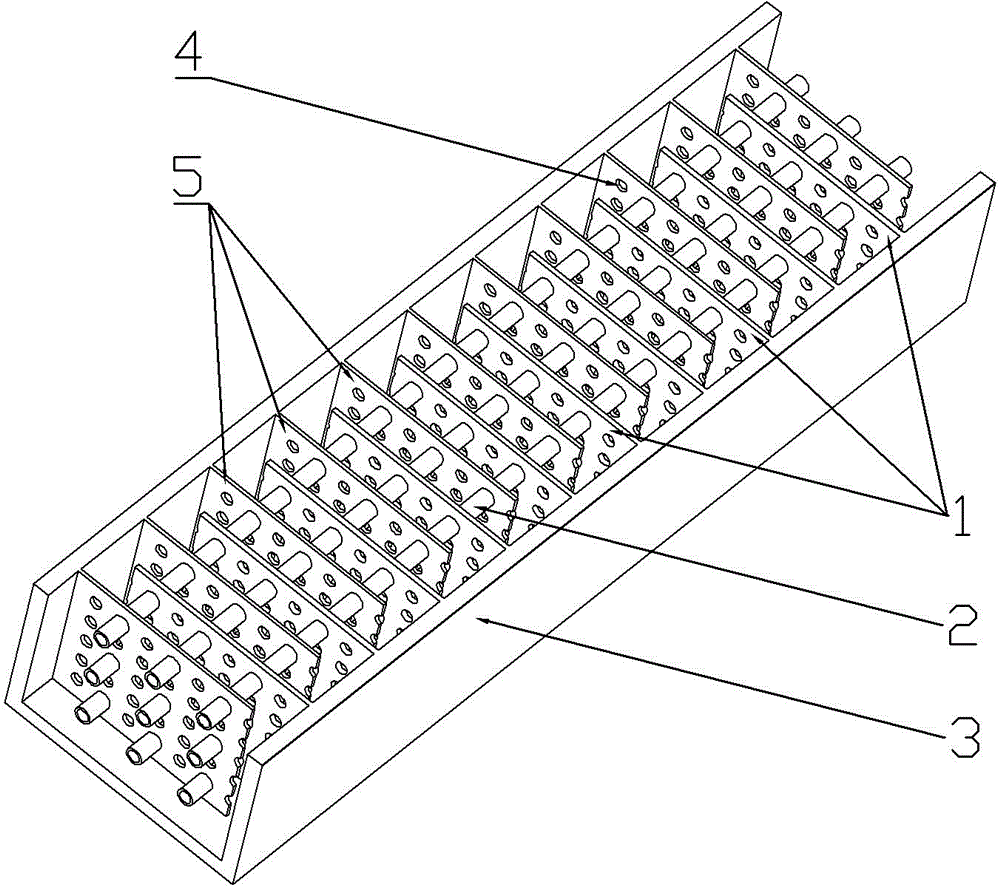
[0014] as attached figure 1 Shown: the present invention comprises the air duct 3 that is fixed on the outer surface of the automobile headlight, and the air duct 3 is a cuboid through cavity, and the direction of the air duct 3 is set according to the air flow direction, that is, the air inlet of the air duct 3 faces the front of the automobile, and the air duct 3 is directed toward the front of the automobile. The air outlet of channel 3 faces the rear of the car. The right cooling fin group 1 and the left cooling fin group 5 are fixed inside the air duct 3, and the outer ends of the cooling fins of the right cooling fin group 1 are equidistantly fixed on the right side wall of the air duct 3, and the heat dissipation of the right cooling fin group 1 There is a gap between the inner end of the sheet and the air duct. The outer ends of the cooling fins of the left cooling fin group 5 are equidistantly fixed on the left side wal...
Embodiment 2
[0016] Embodiment 2 is basically as follows:
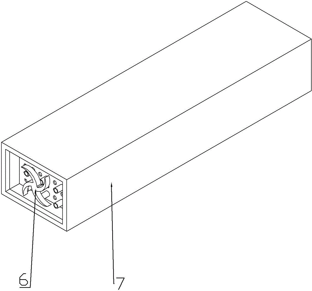
[0017] to combine figure 2 As shown, on the basis of Embodiment 1, a fan is respectively installed at the air inlet and the air outlet of the air duct 3 . When the fan starts, the fan at the air inlet of the air duct 3 will pump the outside air to the inside of the air duct 3, and the fan at the air outlet will discharge the air in the air duct 3 to the outside. In this way, when the car is not moving forward and only the headlights are turned on, the operation of the fan can also cause the air in the air duct 3 to flow.
PUM
 Abstract
Description
Claims
Application Information
 - R&D
- Intellectual Property
- Life Sciences
- Materials
- Tech Scout
- Unparalleled Data Quality
- Higher Quality Content
- 60% Fewer Hallucinations
Browse by: Latest US Patents, China's latest patents, Technical Efficacy Thesaurus, Application Domain, Technology Topic, Popular Technical Reports.
© 2025 PatSnap. All rights reserved.Legal|Privacy policy|Modern Slavery Act Transparency Statement|Sitemap|About US| Contact US: help@patsnap.com