Cabinet system wind resistance test method

A test method and technology for cabinets, applied in the field of cabinets, can solve the problems of over-temperature, long time-consuming, and over-temperature faults of the whole machine, and achieve the effect of solving fan selection, easy operation and high accuracy

Inactive Publication Date: 2015-09-02
ZHUZHOU NAT ENG RES CENT OF CONVERTERS
View PDF2 Cites 2 Cited by
  • Summary
  • Abstract
  • Description
  • Claims
  • Application Information

AI Technical Summary

Problems solved by technology

[0006] 1) The air resistance parameters of the whole system are lacking, the actual operating point of the fan cannot be determined, and the operation of the fan is not in a reasonable area, which leads to the easy damage of the fan and affects the reliability of the product;
[0007] 2) The air resistance parameters of the whole system are lacking, the air volume distribution of the power unit and the dry-type transformer is not suitable, and there is a local overheating phenomenon, which affects product reliability;
[0008] 3) After the whole machine has been running for a period of time, local overheating of the whole machine occurs, and it is difficult to troubleshoot and deal with the overheating problem
[0010] 1) The dry-type transformer used in this kind of cabinet products generally has a cross-flow fan at the bottom. In the current simulation technology, it is difficult to approach the actual situation. Often in the simulation analysis, the cross-flow fan at the bottom is ignored, resulting in simulation data It cannot be realistic, but can only be used as a reference analysis;
[0011] 2) The dry-type transformer has a large number of windings, usually with a complex structure, and it is difficult to balance the effectiveness and timeliness of simulation
Because the air inlet path of the whole machine is different, the running status of the fan is different, and the value obtained from the test is not suitable for the actual situation;
[0015] 3) Only testing the air volume does not ensure that the air volume effectively flowing through the dry-type transformer meets the requirements
As a result, under the premise that the total air volume of the system meets the requirements, local over-temperature faults are frequently reported
[0016] The above three methods cannot effectively obtain the parameter of system wind resistance.
This leads to difficulty in model selection, long time consumption, and excessive fan capacity redundancy

Method used


Image

  • Cabinet system wind resistance test method
  • Cabinet system wind resistance test method
  • Cabinet system wind resistance test method

Examples


Embodiment Construction

[0033] The present invention will be further described below in conjunction with the accompanying drawings and specific embodiments.

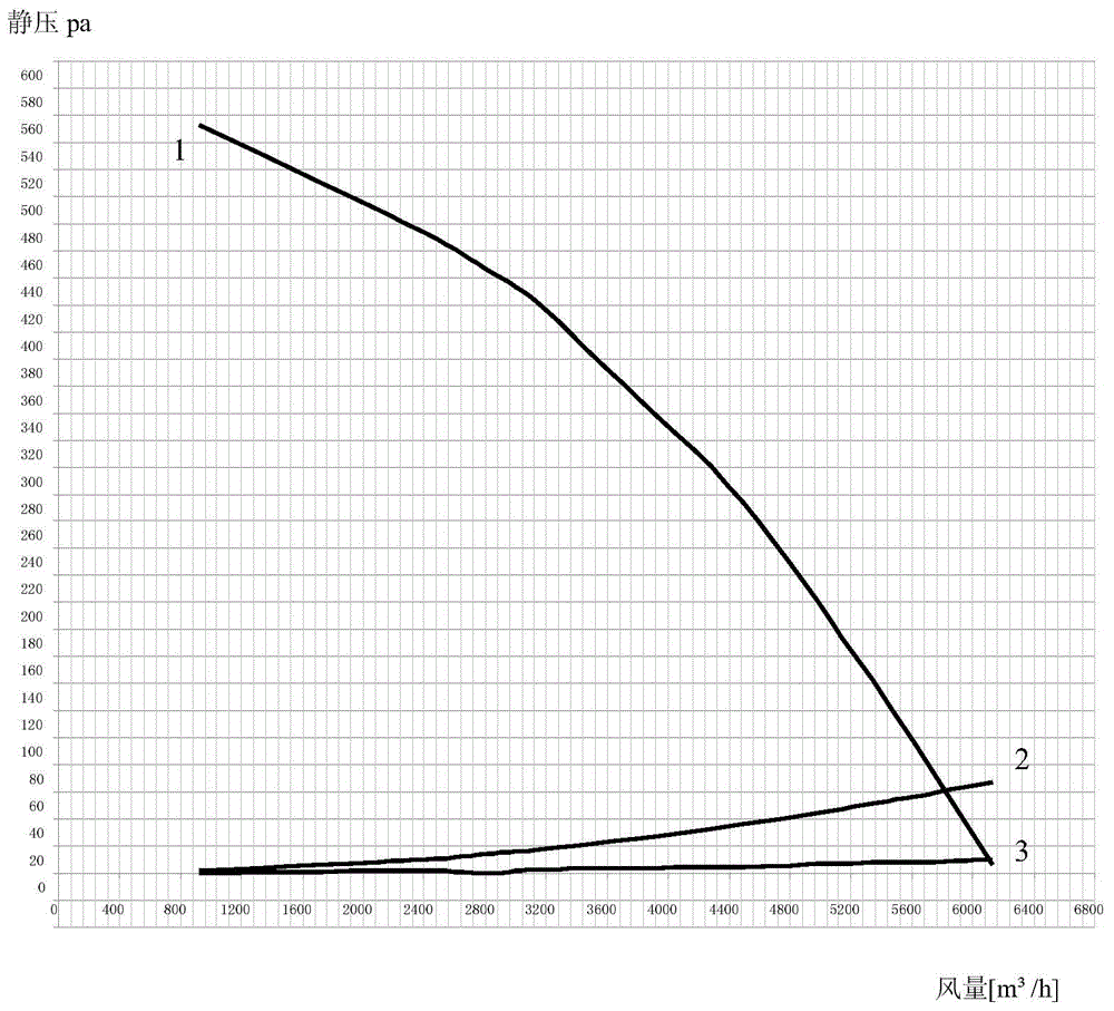
[0034] Such as figure 1 with figure 2 As shown, the method for testing the air resistance of the cabinet system in this embodiment, the method steps of the present invention are as follows:

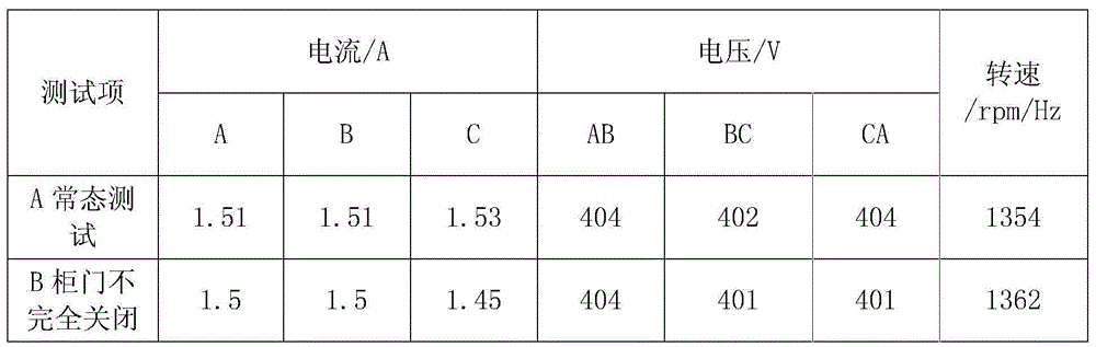
[0035] S1: When the cabinet is powered on and running, measure the operating parameters of the exhaust components of the cabinet under the two working conditions of opening and closing the cabinet door;

[0036] S2: Comparing and analyzing the operating parameters of the exhaust assembly under the two working conditions in step S1 and the factory test data of the exhaust assembly, and obtaining the corresponding air volume Q and static pressure P of the exhaust assembly under the condition of closing the cabinet door, thereby Calculate the resistance coefficient K=P / Q of the cabinet system 2 ;

[0037] S3: Through the resistance coefficient K of the c...


PUM


Abstract

The invention discloses a cabinet system wind resistance test method comprising the following steps: S1, respectively measuring operation parameters of an air-discharge assembly of the cabinet under a cabinet door open and cabinet door close condition when the cabinet is powered up in operation; S2, comparing the operation parameters of the air-discharge assembly under two work conditions in the S1 with delivery test data of the air-discharge assembly so as to obtain an air quantity Q and a static pressure P of the air-discharge assembly under the cabinet door close condition, thus calculating a resistance coefficient of the cabinet system, wherein K=P/Q2; S3, using the cabinet system resistance coefficient K to draft a Q-P real performance curve in a Q-P delivery performance curve map of the air-discharge assembly, and the static pressure P matched with an intersection point between the Q-P delivery performance curve and the Q-P real performance curve is the cabinet system wind resistance value. The cabinet system wind resistance test method is simple in operation, and can accurately obtain the cabinet system wind resistance value.

Description

technical field [0001] The invention mainly relates to the technical field of cabinets, in particular to a method for testing wind resistance of a cabinet system. Background technique [0002] With the rapid development of the economy and the enhancement of people's awareness of energy conservation and environmental protection, the application of inverter devices has become more and more popular, and the scale of the industry has expanded rapidly. The degree of integration and power density of products is getting higher and higher, and the increase in power density has led to the heat dissipation design of the whole machine becoming one of the difficulties in research and development, and the heat dissipation problem has gradually become the main quality problem of this type of product. [0003] As a conventional cabinet-type device at present, the main loss components (several air-cooled power units and dry-type transformers) are placed in a cabinet cavity. The performance...

Claims


Application Information

Patent Timeline
Patent Type & Authority Applications(China)
IPC IPC(8): G01M9/06
Inventor 罗仁俊沈丁建任涛黄欢曹洋周智徐泽连薄晓坤郭倩
Owner ZHUZHOU NAT ENG RES CENT OF CONVERTERS
Why Eureka
Try Eureka