
Push Network Connector

A network connector and sliding technology, which is applied in the direction of connection, two-part connection device, and parts of the connection device, can solve the problems of poor practicability, space occupation, and failure to meet the design requirements of notebook computers, etc., to achieve reduced height, The effect of reducing the occupied space

Active Publication Date: 2018-01-23
上海朋邦实业有限公司
View PDF4 Cites 0 Cited by
  • Summary
  • Abstract
  • Description
  • Claims
  • Application Information

AI Technical Summary

Problems solved by technology

[0004] However, currently used network connectors such as Figure 19 As shown, in the currently used network connector A, the internal insertion space A0 is provided with a plurality of terminals A1, and through the insertion space A0, the network cable plug B is plugged in to perform Internet connection. The size of the network cable plug B is a predetermined specification, so the insertion space A0 of the network connector A must have a certain length and width for the insertion of the network cable plug B, and the size of the network connector A cannot be changed, which also leads to network connection problems. Device A is bulky and takes up space, which does not meet the design requirements of light, thin, short, and small notebook computers, and cannot be used in thin and light or ultra-thin notebook computers.
[0005] Therefore, how to solve the problems and lack of the current network connectors, which are large in size and occupy space, cannot be applied to thin and light or ultra-thin notebook computers, and have poor practicality, is the urgent desire of relevant manufacturers engaged in this industry. The direction of research improvement

Method used


Image

  • Push Network Connector
  • Push Network Connector
  • Push Network Connector

Examples


Embodiment Construction

[0040] In order to achieve the above-mentioned purpose and effect, the technical means and the structure thereof adopted in the present invention are hereby illustrated in detail with respect to the preferred embodiments of the present invention. Its features and functions are as follows, so as to fully understand.

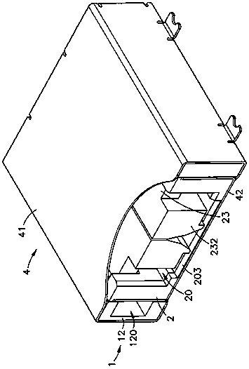
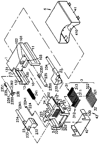
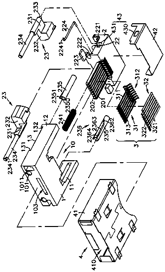
[0041] see Figure 1-4 As shown, it is the three-dimensional appearance diagram, the three-dimensional exploded view, the three-dimensional exploded view in the other direction, and the side sectional view of the present invention. From the figures, it can be clearly seen that the network connector of the present invention includes a base 1, a sliding Shift seat 2, terminal group 3 and shielding case 4, wherein:

[0042] The two sides of the base 1 have side arms 11 and 12 extending in the same direction, and an upper and lower hollow storage space 10 is formed on the opposite inner side of the two side arms 11 and 12, and the space between the two side arms 11 an...


PUM


Abstract

The invention discloses a push-type network connector. A base of the connector is provided with an accommodating space within two side arms. A circulating guide slot is arranged in a sliding space inside one side wall. A sliding seat can be assembled in the accommodating space, so that a guide rod arranged outside the sliding seat can be movably pushed in the circulating guide slot in the sliding space. A terminal group can pass through multiple terminal slots in the wall surface of a plugging space inside the sliding seat. The two sides of the plugging space are respectively provided with a groove for accommodating a rotary frame. The two rotary frames can movably rotate in the grooves at the two sides and can be folded inward into the plugging space of the sliding seat or unfolded outward and matched with the plugging space to form a plugging slot space. Thus, the sliding seat and the two rotary frames can be movably pushed in and go into and out of the accommodating space of the base, and a foldable network connector is formed.

Description

technical field [0001] The invention provides a push-type network connector, especially a network connector that is unfolded or folded by pushing and pressing. A sliding seat is installed inside the base and a shielding shell is installed outside, so that the sliding seat is placed in the base. Moving in and out, the network connector can be expanded to form a network connector, so that the network connector can be movably expanded and folded, and the height of the network connector can be reduced and the occupied space can be reduced after the network connector is folded. Background technique [0002] With the rapid development of today's computer technology, desktop computers or notebook computers have generally existed in every corner of the society. It can be carried and used anywhere, and is not limited by space and location. It is widely loved by the industrial and commercial circles, office workers, and student groups, which makes the usage rate of notebook computers ...

Claims


Application Information

Patent Timeline
Patent Type & Authority Patents(China)
IPC IPC(8): H01R13/502H01R24/64
CPCH01R13/502H01R24/64
Inventor 周肇炎
Owner 上海朋邦实业有限公司
Learn More