Shielding ring and shielding assembly using the same

A technology for shielding rings and components, which is applied in the direction of connecting parts to protect grounding/shielding devices, clamping/spring connections, etc., and can solve problems such as loosening and poor connection reliability of shielding structures

Active Publication Date: 2015-09-02
CHINA AVIATION OPTICAL-ELECTRICAL TECH CO LTD
View PDF5 Cites 1 Cited by
  • Summary
  • Abstract
  • Description
  • Claims
  • Application Information

AI Technical Summary

Problems solved by technology

The structure connected inside the shell mostly adopts the form of shielding ring and compression ring. The shielding ring is connected with the shell, and the shielding layer of the cable is compressed and fixed between the compression ring and the shielding ring. The housing is electrically connected. The problem with this shielding structure is that the compression ring and the shielding ring are rigidly pressed against the shielding layer, so that when the electrical connector is used in a vibrating environment, it is prone to loosening due to vibration. The connection reliability of the structure is not strong

Method used


Image

  • Shielding ring and shielding assembly using the same
  • Shielding ring and shielding assembly using the same
  • Shielding ring and shielding assembly using the same

Examples


Embodiment Construction

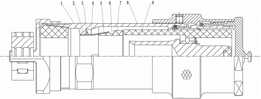
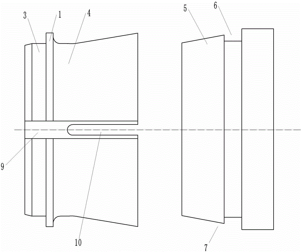
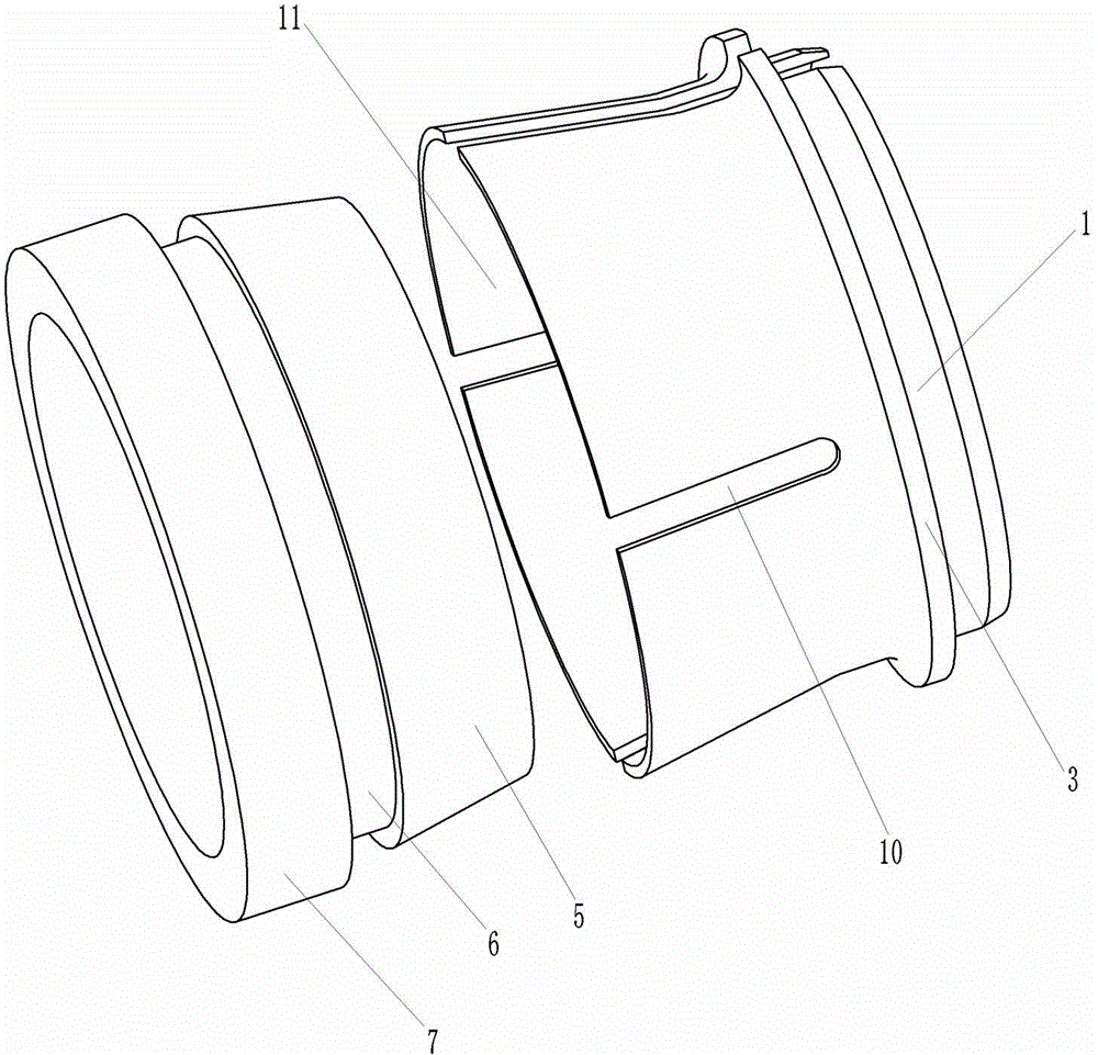
[0019] Examples of shielding components are Figure 1~5 As shown: the shielding ring is used in the electrical connector. The electrical connector includes a housing 8 with a plug-in end at the front end and a shielding assembly arranged in the housing. The shielding assembly includes a shielding ring 4 and a compression ring 7. The shielding ring 4 includes The shielding ring body whose axis is in contact with the housing extends along the front-to-back direction, and the compression ring 7 includes a compression ring body whose axis extends along the front-to-back direction. The hole section 11 is a flaring structure whose diameter gradually increases from the back to the front. In this embodiment, the shielding wire connection hole section 11 is tapered. The front end extending in the direction extends to the crimping deformation groove 10 on the front end surface of the shielding ring body, through the crimping deformation groove, the hole wall of the shielding wire connec...


PUM


Abstract

The invention relates to a shielding ring and a shielding assembly using the same. The shielding ring includes a shielding ring body whose axis extends along a front-back direction, the front end of an inner hole of the shielding body has a shielded wire connecting hole segment for insertion of a rear end wire pressing segment on a corresponding hold-down ring in an anastomotic manner from front to back to be in contact connection with a corresponding shielded wire, the shielded wire connecting hole segment is of a flaring structure whose caliber gradually largens from back to front, and at least two wire pressing deformation grooves whose lengths extend along a front-back direction and front ends extend to a front end face of the shielding ring body are arranged at an interval along a circumferential direction on a hole wall of the shielded wire connecting hole segment. The shielding ring that can elastically press a shielding layer by cooperating with the hold-down ring and the shielding assembly using the shielding ring are provided by the invention.

Description

technical field [0001] The invention relates to a shielding ring in an electrical connector and a shielding assembly using the shielding ring. Background technique [0002] For electrical connectors, it is necessary to connect the shielding layer of the cable to the housing of the electrical connector to achieve shielding of the cable. The existing common shielding methods mainly include two forms: the outside of the housing and the inside of the housing. The structure connected to the outside of the housing is to connect the shielding layer to the terminal attachment of the electrical connector or the terminal reserved on the housing. This form is not suitable for use in outdoor or other harsh environments. The structure connected inside the shell mostly adopts the form of shielding ring and compression ring. The shielding ring is connected with the shell, and the shielding layer of the cable is compressed and fixed between the compression ring and the shielding ring. The ...

Claims


Application Information

Patent Timeline
Patent Type & Authority Applications(China)
IPC IPC(8): H01R13/648H01R4/48H01R4/50
CPCH01R4/48H01R4/50H01R13/648
Inventor 王超
Owner CHINA AVIATION OPTICAL-ELECTRICAL TECH CO LTD
Why Eureka
Try Eureka