Method of reducing adjacent channel interference and relay equipment

A relay device and self-interference technology, applied in the field of communication, can solve the problems of increasing the size of the relay device, increasing the cost of the relay device, and having a larger spacing.

Active Publication Date: 2015-09-02
HUAWEI TECH CO LTD
View PDF8 Cites 15 Cited by
  • Summary
  • Abstract
  • Description
  • Claims
  • Application Information

AI Technical Summary

Problems solved by technology

Compared with scheme 1, scheme 2 relatively reduces the spacing requirements between Rx and Tx, but still has a large requirement for spacing
In addition, due to the need to increase the filter, this will increase the volume of the relay equipment and increase the cost of the relay equipment, and when the volume of the equipment is required to be less than or equal to 0.5m 3 , the backhaul link and the access link must be separated by at least 5MHz, and the backhaul link and the access link cannot be configured as adjacent frequency bands, which will limit the flexibility of backhaul link and access link configuration

Method used


Image

  • Method of reducing adjacent channel interference and relay equipment
  • Method of reducing adjacent channel interference and relay equipment
  • Method of reducing adjacent channel interference and relay equipment

Examples


Embodiment Construction

[0053] The technical solutions in the embodiments of the present invention will be described clearly and in detail below in conjunction with the accompanying drawings in the embodiments of the present invention. Obviously, the described embodiments are only some, not all, embodiments of the present invention. Based on the embodiments of the present invention, all other embodiments obtained by persons of ordinary skill in the art without making creative efforts belong to the protection scope of the present invention.

[0054] In order to better understand the technical solutions of the present invention, the embodiments provided by the present invention will be described in detail below in conjunction with the accompanying drawings.

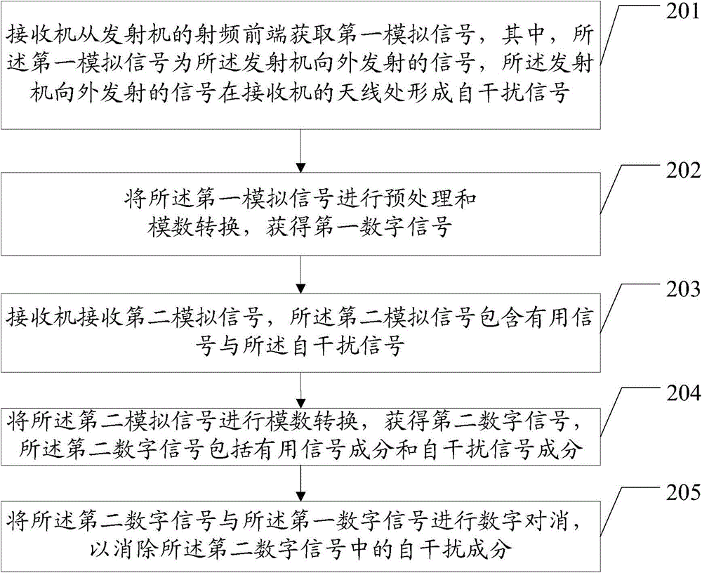
[0055] image 3 is a flow chart of a method for reducing adjacent channel interference provided by an embodiment of the present invention, see image 3 , the method includes:

[0056] 201. The receiver acquires a first analog signal from the rad...


PUM


Abstract

A method for reducing adjacent frequency interference includes: a receiver obtains a first analog signal from the radio frequency front-end of a transmitter, the first analog signal being the signal transmitted to the outside by the transmitter and which forms a self-interference signal in the antenna of the receiver; a first digital signal is obtained by performing analog-to-digital conversion to the first analog signal; the receiver receives a second analog signal including a useful signal and the self-interference signal; a second digital signal is obtained by performing analog-to-digital conversion to the second analog signal; the useful digital signal of the second digital signal is obtained by performing digital cancellation to the second digital signal and the first digital signal. In the present invention, the adjacent frequency interference of signal transmission on signal reception is reduced by means of signal processing without increasing the installation distance between a transmitting antenna and a receiving antenna. Furthermore, the backhaul link and the access link can be configured to be band-adjacent, thereby improving the flexibility of the backhaul link configuration and the access link configuration.

Description

technical field [0001] The invention relates to the field of communication technology, in particular to a method and relay equipment for reducing adjacent frequency interference. Background technique [0002] In a mobile communication network, wireless relay (relay) technology is mainly used for hotspot coverage, cell expansion, emergency, vehicle scenarios, and improving cell coverage. like figure 1 As shown, in the mobile communication network, the wireless relay device 101 can be divided into two parts, one part is used to communicate with the macro station, and the macro station is an evolved base station (evolved Node B, eNB) 102, and this part is called R- The other part of UE104 is used to communicate with user equipment (User Equipment, UE) 103, and this other part is called R-eNB105. The interface between the eNB and the relay device is a backhaul link, and the interface between the relay device and the UE is an access link. In practical applications, configure f...

Claims


Application Information

Patent Timeline
Patent Type & Authority Applications(China)
IPC IPC(8): H04B1/44H04B1/10
CPCH04B1/525H04B7/14H04B15/00
Inventor 林华炯陈卫民李铮铮王情
Owner HUAWEI TECH CO LTD
Why Eureka
Try Eureka