Spurious suppression device and method

A stray suppression device and stray technology, applied in the field of communication, can solve the problems of large influence of receiving sensitivity, large stray interference, and stray interference, and achieve the effect of improving receiving sensitivity and reducing stray interference.

Active Publication Date: 2018-11-27
GUANGDONG OPPO MOBILE TELECOMM CORP LTD
View PDF6 Cites 0 Cited by
  • Summary
  • Abstract
  • Description
  • Claims
  • Application Information

AI Technical Summary

Problems solved by technology

Due to the current high requirements for the miniaturization, thickness and cost of mobile phones, the difficulty of layout and wiring is increasing, resulting in serious spurious problems
[0004] To sum up, the stray interference of communication equipment supporting multiple frequency bands in the prior art is relatively large, resulting in a large impact on receiving sensitivity

Method used


Image

  • Spurious suppression device and method
  • Spurious suppression device and method
  • Spurious suppression device and method

Examples


Embodiment Construction

[0021] In order to make the objectives, technical solutions, and advantages of the present invention clearer, the following further describes the present invention in detail with reference to the accompanying drawings and embodiments. It should be understood that the specific embodiments described here are only used to explain the present invention, but not to limit the present invention.

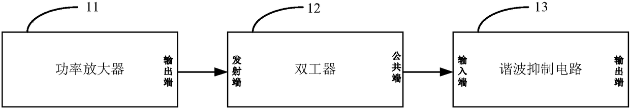
[0022] figure 1 It shows a structural block diagram of a spur suppression device provided by an embodiment of the present invention. For ease of description, only parts related to the embodiment of the present invention are shown. Such as figure 1 As shown, the device includes:

[0023] The power amplifier 11, the duplexer 12 and the harmonic suppression circuit 13, the output end of the power amplifier 11 is connected to the transmitting end of the duplexer 12, and the common end of the duplexer 12 is connected to the input end of the harmonic suppression circuit 13.

[0024] Among them, the h...


PUM


Abstract

The invention is suitable for the technical field of communications, and particularly relates to a spurious suppression device and method. The device comprises a power amplifier, a duplexer and a harmonic suppression circuit, wherein an output end of the power amplifier is connected with a transmitting end of the duplexer; a common port of the duplexer is connected with an input end of the harmonic suppression circuit; and the harmonic suppression circuit is used for controlling input impedance of the harmonic suppression circuit to be matched with output impedance of the harmonic suppression circuit, and controlling resonant frequency of the harmonic suppression circuit to be the same as transmitting frequency of a signal to be transmitted. Through arrangement of the harmonic suppression circuit which is connected with the common port of the duplexer, the input impedance of the harmonic suppression circuit is controlled to be matched with the output impedance, and the resonant frequency of the harmonic suppression circuit is controlled to be the same as the transmitting frequency of the signal to be transmitted, so that the influence of the harmonic suppression circuit on the transmitting frequency of the signal to be transmitted is relatively small; harmonic signals are attenuated greatly; spurious interference can be reduced; and the receiving sensitivity is increased.

Description

Technical field [0001] The invention belongs to the field of communication technology, and particularly relates to a stray suppression device and method. Background technique [0002] Multi-mode multi-frequency mobile phones refer to mobile phones that can be used between networks with different technical standards, that is, a mobile phone can support multiple network standards and multiple network frequency bands at the same time. Before the advent of multi-mode and multi-frequency mobile phones, general handheld devices usually only support dual-mode, that is, support GSM (Global System for Mobile communication) and TD-SCDMA (Time Division-Synchronous Code Division Multiple Access). Code Division Multiple Access), or support GSM and WCDMA (Wideband Code Division Multiple Access, Wideband Code Division Multiple Access). And with 4G (the 4 th With the emergence of Generation mobile communication technology, a large number of 4G mobile phones began to appear. These 4G mobile pho...

Claims


Application Information

Patent Timeline
Patent Type & Authority Patents(China)
IPC IPC(8): H04B1/04H04B1/10
CPCH04B1/0475H04B1/1036H04B2001/1072H04W88/06
Inventor 杨加峰
Owner GUANGDONG OPPO MOBILE TELECOMM CORP LTD
Why Eureka
Try Eureka