
Tooth knife punching die structure for knife bending machine and knife bending machine

A punching die and machete machine technology, applied in the direction of manufacturing tools, other manufacturing equipment/tools, etc., can solve the problems of punching precision impact, frequent mold adjustment, etc., and achieve the effect of height adjustment guarantee

Active Publication Date: 2015-09-09
RICHLY TOP CNC EQUIP SHENZHEN CO LTD
View PDF7 Cites 5 Cited by
  • Summary
  • Abstract
  • Description
  • Claims
  • Application Information

AI Technical Summary

Problems solved by technology

In addition, frequent mold adjustments due to changes in the width of the gear cutter, and the contact gap between the blade and the mold have a great impact on the punching accuracy when the gear cutter is punching, which also plagues those skilled in the art.

Method used


Image

  • Tooth knife punching die structure for knife bending machine and knife bending machine
  • Tooth knife punching die structure for knife bending machine and knife bending machine
  • Tooth knife punching die structure for knife bending machine and knife bending machine

Examples


Embodiment 1

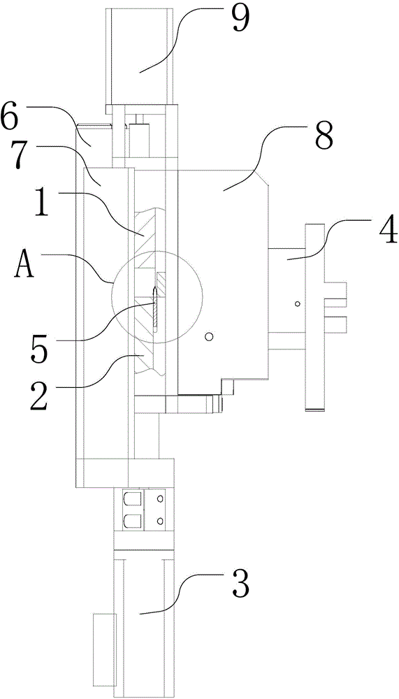
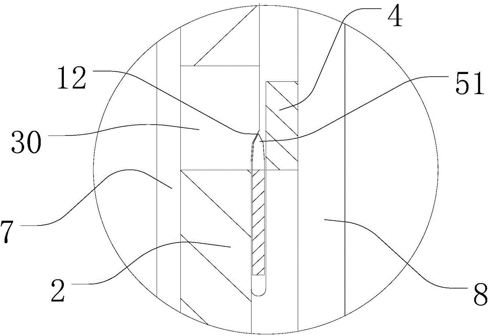
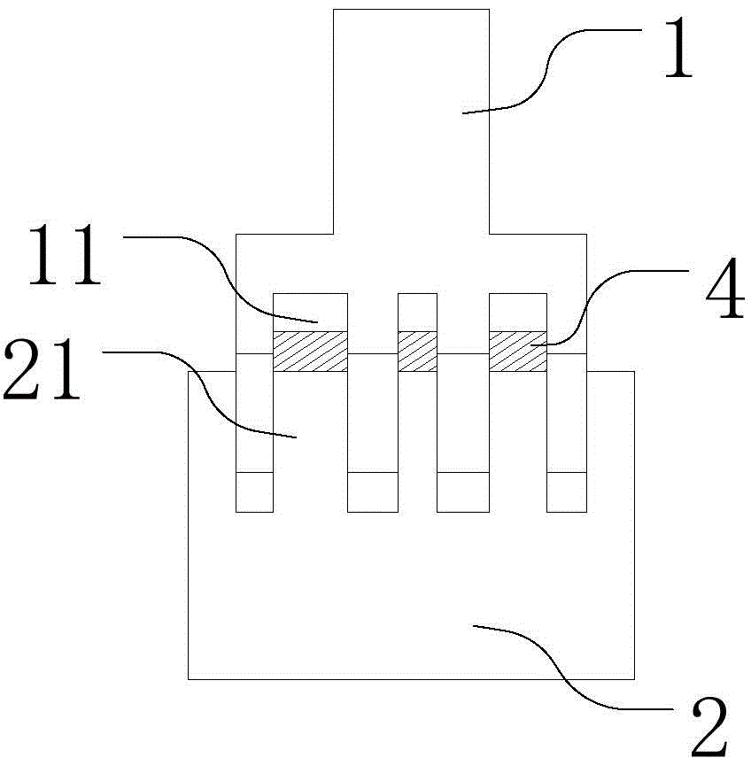
[0021] The embodiment of the present invention provides a punching die structure with a gear knife for a machete machine, combining Figure 1 to Figure 3 As shown, it includes: pillow mold 1, bottom mold 2, bottom mold driving mechanism 3, punching male mold 4, pillow mold 1 and bottom mold 2 are located on the same side, punching male mold 4 is located on the opposite side, pillow mold 1 1. Between the bottom mold 2 and the punching male mold 4, a blade channel for the passage of the blade is formed. The lower end surface of the pillow mold 1 is provided with a groove 11 that runs through the front and back and matches the width of the punching male mold. The upper end surface of the bottom mold 2 is provided with The bump 21 matching the width of the groove 11, the pillow mold 1 and the bottom mold 2 are set up and down oppositely, and the groove 11 is matched with the bump 21 to form a die matching the width of the punching die 3 hole 30, the bottom mold 2 is driven by the ...

Embodiment 2

[0030] A machete machine is provided in this embodiment, which includes a toothed knife punching die, a blade grinding device and a machete device, wherein the blade grinding device and the machete device all adopt the structure of the prior art. Needless to repeat, the gear knife punching die adopts the structure of the gear knife punching die for a machete machine in the above-mentioned embodiment 1. For the specific structure and working principle, reference may be made to the description in Embodiment 1 above in detail, and details are not repeated here.


PUM


Abstract

The invention discloses a tooth knife punching die structure for a knife bending machine and the knife bending machine. The die structure comprises a pillow-position die, a bottom die, a bottom die drive mechanism and a punching male die; and the lower end face of the pillow-position die is provided with groove which penetrates the front and the rear and which matches the punching male die in width, the upper end face of the bottom die is provided with a protruding block which matches the groove in width, the pillow-position die and the bottom die are disposed in an up-down relative manner, the groove and the protruding block are disposed in a matching and sleeving manner to form a die hole matching the punching male die in width, and the bottom die is driven by the bottom die drive mechanism to move in the vertical direction so that the height of the die hole relative to a blade is changed. The pillow-position die and the bottom die are adopted to together form a mother die, the bottom die slides relative to the pillow-position die so that the height of the die hole relative to the blade is adjustable; and the bottom die and the pillow-position die form the die hole adopting a groove-block matching mode, so the blade can be guaranteed to be completely abutted except for at a punching position, tooth knife height adjustments are achieved, and the punching effect is guaranteed at the same time.

Description

technical field [0001] The invention relates to the technical field of a machete machine, in particular to a punching die structure with a gear cutter for a machete machine and a machete machine. Background technique [0002] The machete machine is widely used in the production of high-precision knife templates such as electronics and optoelectronics. Today's electronics, printing and packaging industries are developing rapidly, and as a supporting industry - die-cutting board (mold cutting) processing industry has been greatly developed. With the increase of market share, more and more enterprises and funds have entered the industry, which has caused the die-cutting industry, which was originally very profitable, to enter a difficult situation. However, in the market competition where price is the main factor, in addition to reducing production costs, improving production efficiency is also an important factor for winning the competition. As one of the two core equipments...

Claims


Application Information

Patent Timeline
Patent Type & Authority Applications(China)
IPC IPC(8): B21D28/14
CPCB21D28/14B23P23/00
Inventor 伍昌铭江鸿鹄
Owner RICHLY TOP CNC EQUIP SHENZHEN CO LTD
Learn More