A T-shaped rotor wing low-speed anti-sway device

A technology of anti-rolling device and rotor wing, which is applied in the direction of using hydrofoils to reduce the movement of ships on the surrounding water surface, and can solve the problems of no anti-rolling effect, poor anti-rolling effect, poor anti-rolling effect, etc., and achieve improvement Effect of riding or working environment, compensating for poor effect, improving seakeeping and airworthiness

Active Publication Date: 2017-02-22
HARBIN ENG UNIV
View PDF5 Cites 0 Cited by
  • Summary
  • Abstract
  • Description
  • Claims
  • Application Information

AI Technical Summary

Problems solved by technology

However, the traditional T-shaped hydrofoil has a good anti-rolling effect only at high speeds, that is, it is only suitable for high-speed ships. Poor or no stabilization

Method used


Image

  • A T-shaped rotor wing low-speed anti-sway device
  • A T-shaped rotor wing low-speed anti-sway device
  • A T-shaped rotor wing low-speed anti-sway device

Examples


Embodiment Construction

[0020] The present invention will be further described in detail below in conjunction with the accompanying drawings and specific embodiments.

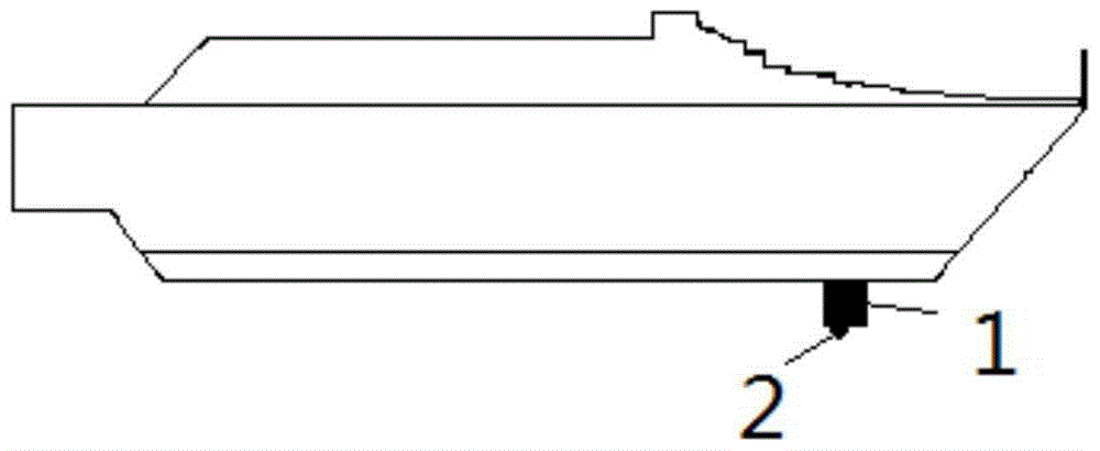
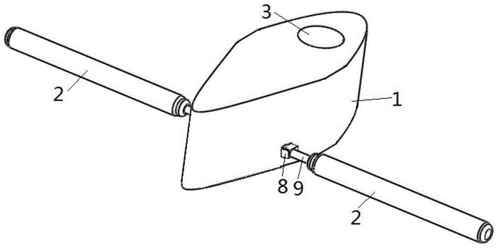
[0021] combine Figure 1 to Figure 7 , including a column 1 and a horizontal rotor cylinder 2 symmetrically arranged on both sides of the column, two hydraulic cylinders 4 are symmetrically arranged in the column 1, and the end of the piston rod 5 of each hydraulic cylinder 4 is connected to the set by a living hinge 7 One end of the first moment arm 6 in the column 1 is hinged, and the other end of each first moment arm 6 is all hinged with one end of the second moment arm 9 by a fixed hinge 8 arranged on the column 1, each of the The horizontal rotor cylinder 2 is provided with a rotor piston 14, and the outer surface of the rotor piston 14 is attached to the inner surface of the horizontal rotor cylinder 2, and each rotor piston 14 is provided with a motor 12, and the output of each motor 12 The end of the shaft 16 is fixedly conn...


PUM


Abstract

The invention provides a T-shaped rotor foil low-speed stabilization apparatus. The T-shaped rotor foil low-speed stabilization apparatus comprises a column and horizontal rotor cylinders, the upper end of the column is fixed at the bottom of a ship, the lower end of the column is connected with the horizontal rotor cylinders, hydraulic cylinders are positioned at the inner part of the column, the hydraulic cylinders drive the horizontal rotor cylinders to swing back and forth, and motors at the inner parts of the horizontal rotor cylinders drive the horizontal rotor cylinders to rotate. At the zero speed, a T-shaped rotor foil is driven by the hydraulic cylinders, the horizontal rotor cylinders swing to a position vertical to the water-flow direction and swing back and forth regarding the position as the initial position, and the motors at the inner parts of the horizontal rotor cylinders drive the horizontal rotor cylinders to rotate; at the low speed, the horizontal rotor cylinders swing to the position vertical to the water-flow direction, and the motors at the inner parts of the horizontal rotor cylinders drive the horizontal rotor cylinders to rotate. According to the stabilization apparatus, the ship sea-keeping can be improved, when the T-shaped rotor foil does not need to operate, the horizontal rotor cylinders are taken back to the tail part of the column driven by the hydraulic cylinders, the navigation resistance can be reduced, fuels are saved, and the speed is increased.

Description

technical field [0001] The invention relates to an anti-rolling device, in particular to a low-speed anti-rolling device for a T-shaped rotor blade. Background technique [0002] With the rapid development of the maritime transport industry, all kinds of ships have increased. Catamaran is one of the most widely used ship types. Catamarans are generally favored for their large deck area, large cabin space, and convenience for luxurious decoration. They have become a type of ship that has developed rapidly, is widely used, and has a large number of constructions in recent years. Since the width of the catamaran is much larger than that of the monohull, its stability is obviously better than that of the monohull, and it has the ability to withstand relatively large wind and waves. The catamaran not only has good maneuverability, but also has a resistance peak that is not obvious. , Large loading capacity and other characteristics, so it is widely used as military ships and ci...

Claims


Application Information

Patent Timeline
Patent Type & Authority Patents(China)
IPC IPC(8): B63B39/06
Inventor 梁利华油兴田张永庆史洪宇张松涛苑佳杜雪任振飞
Owner HARBIN ENG UNIV
Why Eureka
Try Eureka