
Material transfer device based on compound parallelogram mechanism

A parallelogram, transfer device technology, applied in the direction of lifting device, hoisting device, etc., to achieve the effect of large transfer range, enlarged transfer stroke, and simple structure

Inactive Publication Date: 2015-09-09
SHANGHAI AEROSPACE SYST ENG INST
View PDF8 Cites 0 Cited by
  • Summary
  • Abstract
  • Description
  • Claims
  • Application Information

AI Technical Summary

Problems solved by technology

[0004] The object of the present invention is to provide a material transfer device based on a composite parallelogram mechanism to solve the problem that in some narrow spaces in the prior art, the travel of material transfer is generally required to be longer, and the structure is simple and the weight is light. The technical problem that the material transfer device cannot meet the requirements

Method used


Image

  • Material transfer device based on compound parallelogram mechanism
  • Material transfer device based on compound parallelogram mechanism
  • Material transfer device based on compound parallelogram mechanism

Examples


Embodiment 1

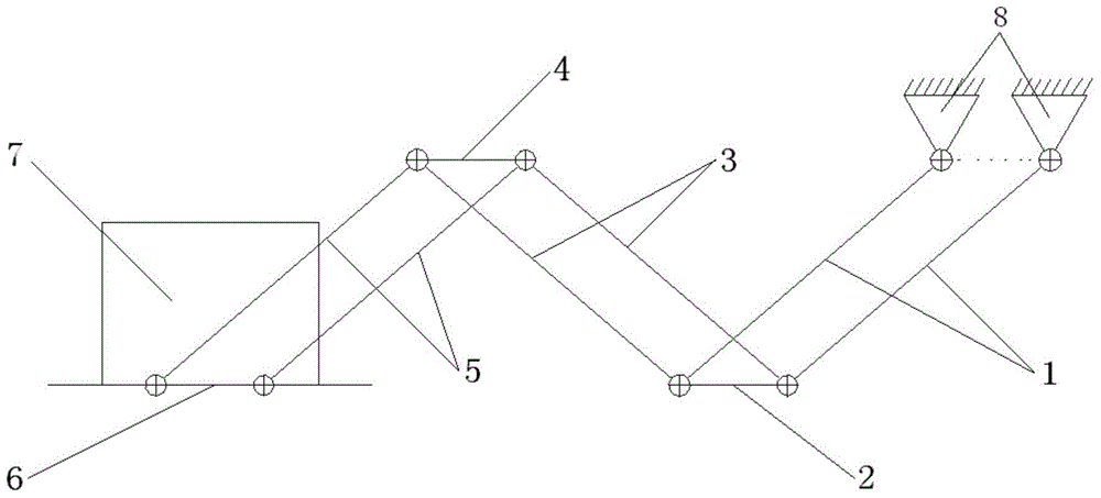
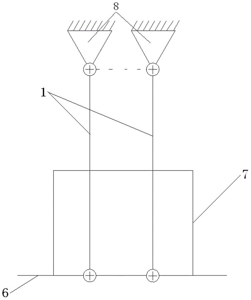
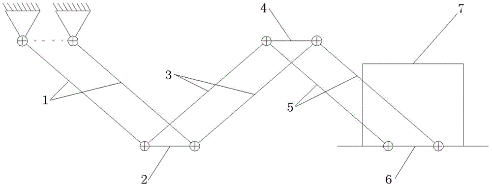
[0020] see Figure 1-3 , a material transfer device based on a compound parallelogram mechanism, including a driving device, a support 8, a connecting rod assembly I, a connecting rod II2, a connecting rod frame assembly, a connecting rod assembly X and a supporting plate 6, wherein,

[0021] The connecting rod assembly I includes two connecting rods I1, one end of the two connecting rods I1 is hinged to the support 8, and the other end is respectively hinged to the two ends of the connecting rod II2, and the two connecting rods I1 are parallel It is set that the driving device is connected to the connecting rod I1, and the driving device can drive the connecting rod I1 to swing;

[0022] The connecting rod frame assembly includes connecting rod IV4 and two connecting rods III3, one end of the two connecting rods III3 is respectively hinged to the two ends of the connecting rod II2, and the other end is respectively connected to the two ends of the connecting rod IV4 Hinged, ...


PUM


Abstract

The invention provides a material transfer device based on a compound parallelogram mechanism. The material transfer device comprises a driving device, a support, a first connecting rod assembly, a second connecting rod, a connecting rod frame module, a connecting rod assembly X and a supporting plate. The first connecting rod assembly comprises two first connecting rods, the two ends of the two first connecting rods are hinged to the support and the second connecting rod, and the driving device is connected with the first connecting rods. The connecting rod frame module comprises a fourth connecting rod and two third connecting rods, the ends of the two third connecting rods are hinged to the two ends of the second connecting rod respectively, and the other ends of the two third connecting rods are hinged to the two ends of the fourth connecting rod respectively. The connecting rod assembly X comprises two connecting rods X, the ends of the two connecting rods X are hinged to the two ends of the fourth connecting rod, and the other ends of the connecting rods X are hinged to the supporting plate. Compared with the prior art, the material transfer device is large in transfer range and simple in structure, a device body is small in occupied space, easy to operate and high in reliability and can be widely applied to the occasions with narrow space and large material transfer stroke, and an effective solution is provided for large-stroke transfer of materials in a narrow space.

Description

technical field [0001] The invention relates to a material transfer device, in particular to a material transfer device based on a composite parallelogram mechanism. Background technique [0002] The existing material transfer device is mainly based on a one-way double-stroke mechanism, which is often used in the lifting mechanism of a forklift, and the lifting height is limited by the stroke of the hydraulic cylinder. [0003] In some occasions where the space is small, it is generally required that the material transfer has a long stroke, and requires a simple structure and light weight, but the current material transfer device cannot meet the requirements. Contents of the invention [0004] The object of the present invention is to provide a material transfer device based on a composite parallelogram mechanism to solve the problem that in some narrow spaces in the prior art, the travel of material transfer is generally required to be longer, and the structure is simple ...

Claims


Application Information

Patent Timeline
Patent Type & Authority Applications(China)
IPC IPC(8): B66F19/00
CPCB66F19/00
Inventor 谢哲靳宗向
Owner SHANGHAI AEROSPACE SYST ENG INST
Learn More