Energy-saving control method, system and device of combined gas condensing heat supply system

An energy-saving control system and heating system technology, applied in the direction of air heaters, fluid heaters, lighting and heating equipment, etc., can solve the problems of large footprint, inability to achieve reasonable load distribution and transfer, load fluctuations, etc.

Active Publication Date: 2015-09-09
SUZHOU TLEP CLIMATE TECH CO LTD
View PDF7 Cites 2 Cited by
  • Summary
  • Abstract
  • Description
  • Claims
  • Application Information

AI Technical Summary

Problems solved by technology

[0007] The technical problem to be solved by the present invention is that it is difficult to meet the needs of large-area heating and various needs of customers in the current single gas condensing heating system, and the power cannot be adjusted flexibly, and there is an area occupied when multiple gas condensing heating single units are used together. Large area, inconvenient installation and many other shortcomings, especially when ...

Method used


Image

  • Energy-saving control method, system and device of combined gas condensing heat supply system
  • Energy-saving control method, system and device of combined gas condensing heat supply system
  • Energy-saving control method, system and device of combined gas condensing heat supply system

Examples


Embodiment 1

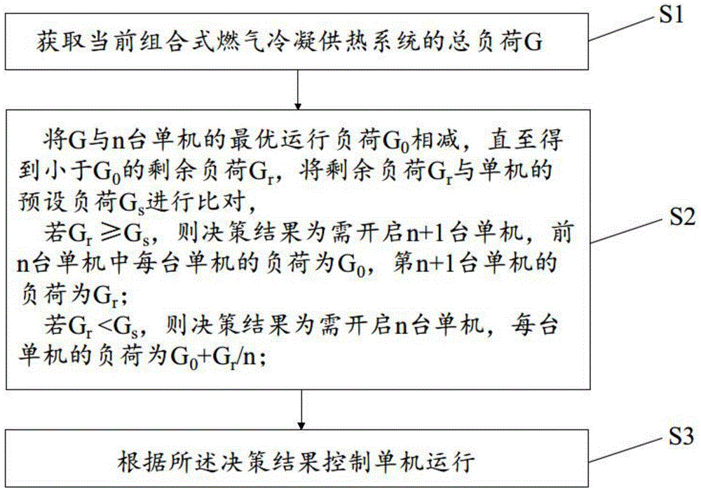
[0078] like figure 1 As shown, the present invention provides an energy-saving control method for a combined gas-fired condensing heating system. multiple gas-fired condensing heating units, the optimal operating load of each unit is G 0 , the method includes the following steps:

[0079] Assuming that when a single machine is running at full load, its load is G imax = 350KW, stand-alone operating efficiency η = 91.4%, then according to the formula η = G i / G imax , then G i =G 0 , calculate the optimal operating load G of a single machine 0 is 320KW.

[0080] S1. Obtain the total load G of the current combined gas condensing heating system;

[0081] Assume that the total load G of the current system is 1000KW.

[0082] S2. Compare G with the optimal operating load G of n single machines 0 subtract until you get less than G 0 The residual load G r , the residual load G r Preset load G with stand-alone s to compare,

[0083] If G r ≥G s , the decision result is...

Embodiment 2

[0150] like figure 1 As shown, the present invention provides an energy-saving control method for a combined gas-fired condensing heating system. multiple gas-fired condensing heating units, the optimal operating load of each unit is G 0 , the method includes the following steps:

[0151] Assuming that when a single machine is running at full load, its load is G imax = 500KW, stand-alone operating efficiency η = 95%, then according to the formula η = G i / G imax , then G i =G 0 , calculate the optimal operating load G of a single machine 0 is 475KW.

[0152] S1. Obtain the total load G of the current combined gas condensing heating system;

[0153] Assume that the total load G of the current system is 2500KW.

[0154] S2. Compare G with the optimal operating load G of n single machines 0 Subtract until you get less than G 0 The residual load G r , the residual load G r Preset load G with stand-alone s to compare,

[0155] If G r ≥G s , the decision result is t...


PUM


Abstract

The invention discloses an energy-saving control method of a combined gas condensing heat supply system. The method is characterized in that the system comprises a main controller, and a plurality of gas condensing heat supply single units which are connected with the main controller; the optimal operation load of each single unit is G0. The method comprises the steps of S1, acquiring the current total load G of the system; S2, subtracting G from G0 until obtaining the rest load Gr less than G0, comparing the Gr with the preset load Gs of the single units, starting n+1 single units if Gr is not less than Gs, wherein the load of each of the front n single units is G0, and the load of the (n+1)th single unit is Gr; starting n single units if Gr is less than Gs, wherein the load of each single unit is G0+Gr/n; S3, controlling the single units to run according to the decision making result. The invention further discloses an energy saving control system and device of the combined gas condensing heat supply system. According to the method, the operation load of single gas condensing heat supply unit is reasonably distributed according to the real-time heat supply demand, so that the energy can be saved to the maximum.

Description

technical field [0001] The invention relates to the field of energy-saving control of condensing boilers, in particular to a method, system and device for energy-saving control of a combined gas-fired condensing heating system. Background technique [0002] The gas condensing heating system is a new type of high-efficiency environmental protection system that uses 100% complete premixing technology of gas and air before entering the heat exchanger for combustion; The body of the device goes through the process of cooling and condensation, recovering most of the latent heat of vaporization of the water vapor in the flue gas, greatly improving the system efficiency and effectively reducing the exhaust gas temperature. [0003] Compared with the traditional atmospheric gas boiler, the gas condensing heating system is more energy-saving, environmentally friendly and efficient because of the new combustion method of 100% premixed combustion and the structural design of the integr...

Claims


Application Information

Patent Timeline
IPC IPC(8): F24H9/20F24H8/00
CPCY02B30/00
Inventor 王文星王耀
Owner SUZHOU TLEP CLIMATE TECH CO LTD
Why Eureka
Try Eureka