
Drum Type Gas Jet Impact Dryer

A gas jet and drum type technology, applied in the direction of non-progressive dryers, dryers, drying solid materials, etc., can solve the problems of operation, small heat capacity coefficient, unfavorable feeding and discharging, etc.

Active Publication Date: 2016-10-26
SHIHEZI UNIVERSITY
View PDF8 Cites 0 Cited by
  • Summary
  • Abstract
  • Description
  • Claims
  • Application Information

AI Technical Summary

Problems solved by technology

The disadvantage of this design is that its structure is designed in batches, which is not conducive to feeding and discharging, and cannot meet the needs of industrial production.
However, due to the disadvantages of low thermal efficiency (except for the steam tube type drum dryer), small heat capacity coefficient, and difficult installation of the rotary drum dryer, the drying system cannot be operated in an optimal state, so there is still a big problem for the rotary drum dryer. Optimize space: improve drying efficiency and reduce energy waste

Method used


Image

  • Drum Type Gas Jet Impact Dryer
  • Drum Type Gas Jet Impact Dryer
  • Drum Type Gas Jet Impact Dryer

Examples


Embodiment 1

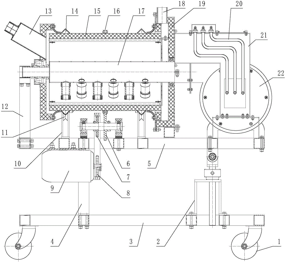
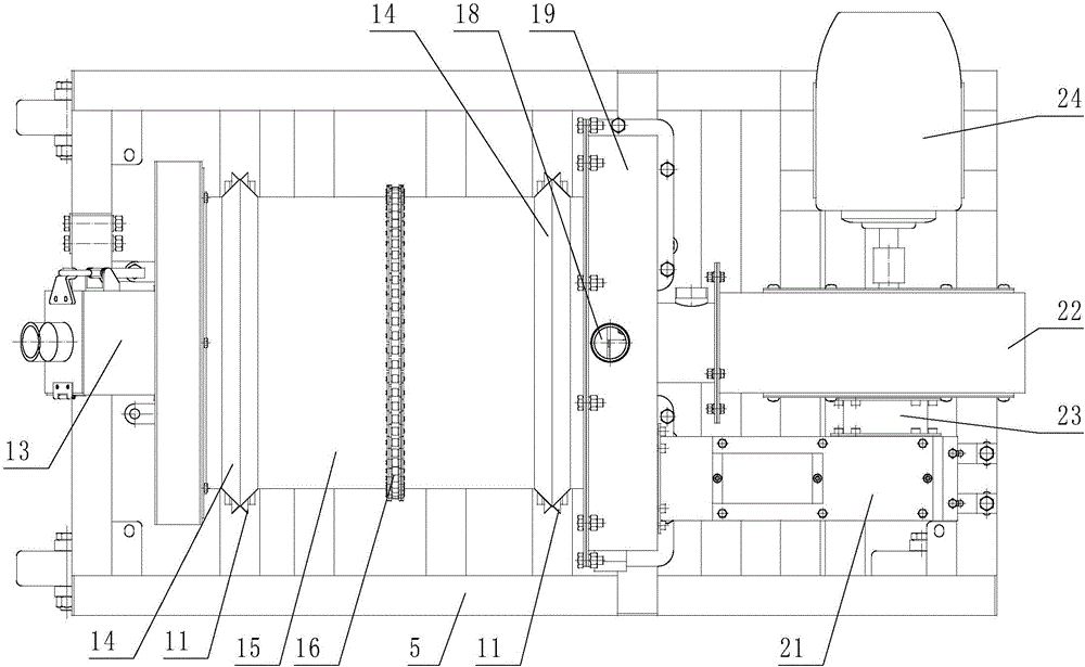
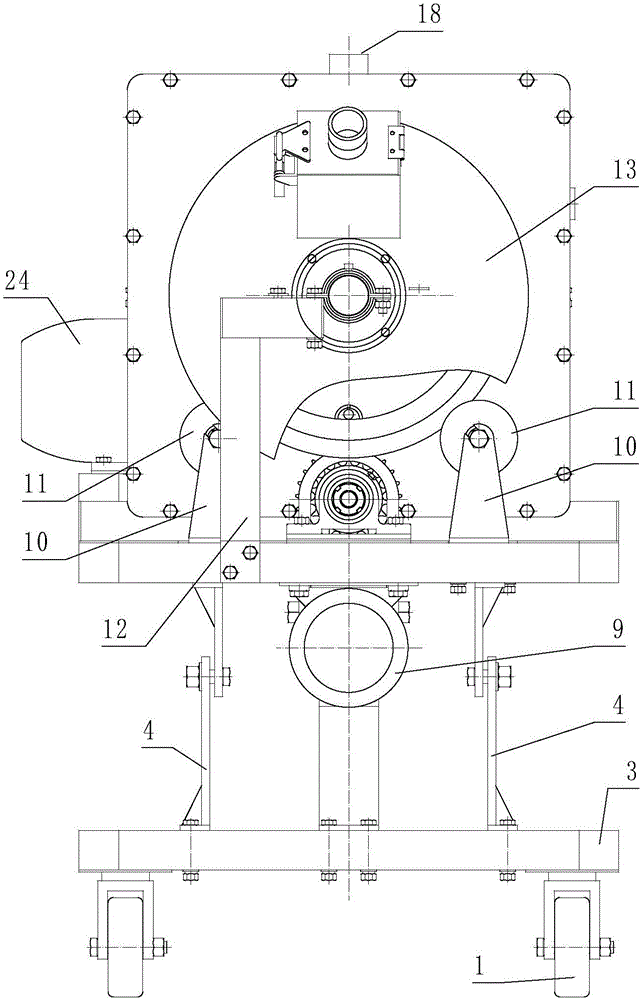
[0070] Referring to the accompanying drawings: a drum type gas jet impact dryer mainly includes a main frame 3 and a walking wheel 1, a vehicle frame 5 is provided above the general frame 3, and a centrifugal fan 22 is provided above the vehicle frame 5 , heater 21, material drum 15, transmission group;

[0071] The structure of the heater 21 mainly includes a heater housing 21-1, the heater housing 21-1 is provided with an air inlet 21-3 and an air outlet 21-2, and the heater housing 21-1 There is an electric heating tube 20 inside;

[0072]The structure of the material drum 15 mainly includes a cylinder body 15-1, one side of the cylinder body 15-1 is provided with a return air end box 19, and the other side is provided with a feeding and discharging mechanism 13, and the cylinder body 15-1 There is an airflow impact mechanism 17 inside;

[0073] The cylinder 15-1 is a hollow shell with a central rotating shaft 15-3, one end of the cylinder 15-1 is provided with a sieve pl...

Embodiment 2

[0081] Compared with Embodiment 1, the difference of this embodiment is that the overall frame 3 and the vehicle frame 5 are connected with the lifting mechanism 2 through the overall frame bracket 4, and the overall frame bracket 4 is close to the material drum 15 Its structure includes the upper part 4-2 of the bracket group and the lower part 4-1 of the bracket group, and the upper part 4-2 of the bracket group and the lower part 4-1 of the bracket group are hinged to each other; the structure of the lifting mechanism 2 includes lifting Seat 2-4, lifting screw rod 2-1, lifting nut 2-3, described lifting seat 2-4 is fixedly connected with main frame 3, and lifting nut 2-3 is arranged on the top of described lifting seat 2-4, and lifting nut 2-3 is provided with a lifting torsion bar 2-5, the lifting screw 2-1 passes through the lifting nut 2-3 and the lifting seat 2-4, and the lifting screw 2-1 and the lifting nut 2-3 are threaded Connected, the upper part 2-2 of the lifting...

Embodiment 3

[0083] Compared with Embodiment 2, the difference of this embodiment is that the structure of the transmission group includes a driving gear 8, a driven pinion 7, a driven large gear 6, the driving gear 8 is connected with the motor II 9, and the driving gear 8 is driven by a chain with the driven pinion 7, the driven pinion 7 and the driven large gear 6 are coaxially connected, and the driven large gear 6 is meshed with the chain 16 on the material drum 15.


PUM


Abstract

The invention belongs to the technical field of agricultural product processing, and relates to a drum-type gas jet impingement drier. The drum-type gas jet impingement drier mainly comprises a primary rack and walking wheels. A frame is arranged above the primary rack. A centrifugal fan, a heater, a material drum, and a transmission unit are arranged above the frame. The structure of the material drum mainly comprises a drum body; one side of the drum body is provided with an air-return end box body, and the other side of the drum body is provided with a feed-discharge mechanism; and a gas impingement mechanism is arranged inside the drum body. Provided is a drum-type gas jet impingement drier which is reasonable in structure, high in gas impingement drying heat conduction factor, strong in adaptability to materials, high in drying production capacity, capable of being used for different sizes of products, wide in application range, economical and practical.

Description

technical field [0001] The invention belongs to the technical field of agricultural product processing, and relates to a drum type pulsating gas jet impingement dryer for agricultural products. Background technique [0002] Gas jet impingement drying technology is a drying technology that sprays heated gas with a certain pressure through a nozzle of a certain shape, and directly impacts the surface of the material. From the boundary layer theory, due to the high flow velocity of the gas jet, a very thin boundary layer will be formed between the main air flow and the surface of the material when it hits the material at a close distance, so it has a high velocity gradient and temperature gradient, and can In a short period of time, the material reaches or approaches the temperature of the impinging air flow and quickly takes away the evaporated moisture. Therefore, the convective heat transfer coefficient of the gas jet impingement drying is several times or even an order of m...

Claims


Application Information

Patent Timeline
Patent Type & Authority Patents(China)
IPC IPC(8): F26B11/06F26B21/00F26B25/00F26B25/02F26B25/04
Inventor 姚雪东王高黄勇朱容光王栋薛令阳
Owner SHIHEZI UNIVERSITY
Learn More