Clamp for fixing optical fiber reinforcing member

A reinforcement and fixture technology, which is applied in the field of fixtures for fixing optical cable reinforcements, can solve problems such as broken reinforcements and failure to fix, and achieve the effects of guaranteed tensile force value, convenient and fast operation, and long-term safe operation

Active Publication Date: 2015-09-09
四川天府江东科技有限公司
View PDF6 Cites 4 Cited by
  • Summary
  • Abstract
  • Description
  • Claims
  • Application Information

AI Technical Summary

Problems solved by technology

[0002] The lightweight lightning protection optical cable adopts a non-metallic structure, so its reinforcements are made of non-metallic materials. One structure is two parallel FRP outside the central tube as reinforcements, and the other structure is coated with glass fiber tape outside the central tube. As a strength member, the steel wire is fixed by screws in the general optical cable splice box or fiber distribution box, which will easily cause the breakage of the strength member or cannot be fixed at all when fixing two parallel FRP material or glass fiber tapes.

Method used


Image

  • Clamp for fixing optical fiber reinforcing member
  • Clamp for fixing optical fiber reinforcing member
  • Clamp for fixing optical fiber reinforcing member

Examples


Embodiment 1

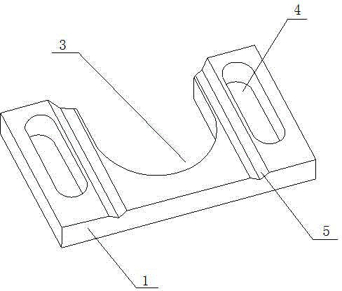
[0015] like Figure 1 to Figure 3 As shown, a clamp for fixing an optical cable strength member includes a rectangular upper clamp 1 and a lower clamp 2, the upper clamp and the lower clamp have the same length and width and are placed in reverse. There is a "U"-shaped mouth-3 in the middle of the long side of the upper fixture 1, and a chute 4 is provided on both sides of the "U"-shaped mouth-3, and a "V" is opened between the chute 4 and the "U"-shaped mouth-3. "shaped groove-5; chute 4 is convenient for the upper and lower clamps to fix the metal fixing parts in the optical cable joint box and fiber distribution box, and is suitable for metal fixing columns of different sizes.

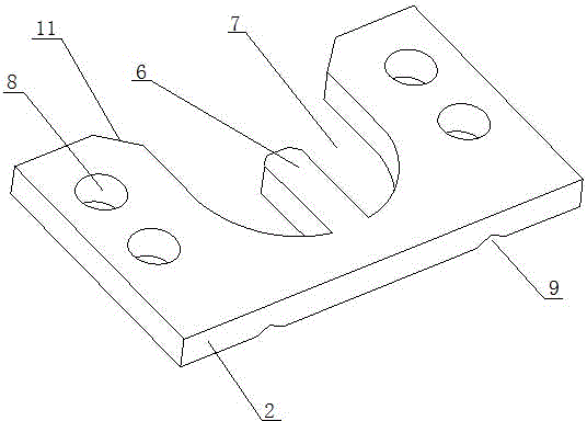
[0016] In the middle of the long side on one side of the lower fixture 2, there is a "U" shaped mouth 2 7 that is the same size as the "U" shaped mouth 1 3, and the two sides of the "U" shaped mouth 7 are provided with screw holes 8. Preferably, there are two holes on each side. There are two screw...

Embodiment 2

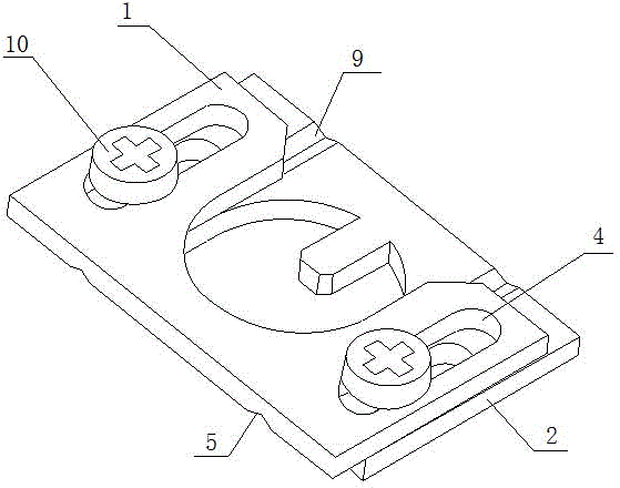
[0022] like figure 1 , figure 2 and Figure 4 As shown, a clamp for fixing an optical cable strength member includes a rectangular upper clamp 1 and a lower clamp 2, the upper clamp and the lower clamp have the same length and width and are placed in the same direction. There is a "U"-shaped mouth-3 in the middle of the long side of the upper fixture 1, and a chute 4 is provided on both sides of the "U"-shaped mouth-3, and a "V" is opened between the chute 4 and the "U"-shaped mouth-3. " shaped groove one 5; the middle of the long side on one side of the lower fixture 2 has a "U" shaped mouth two 7 of the same size as the "U" shaped mouth one 3, and two sides of the "U" shaped mouth two 7 are provided with screw holes 8, Preferably there are two screw holes on each side, wherein the length of the chute 4 is greater than the longest connecting line between the two screw holes 8 . There is a fixed shaft core 6 in the middle of the "U"-shaped mouth 2 7, which is used to fix t...


PUM


Abstract

The invention discloses a clamp for fixing an optical fiber reinforcing member. The clamp comprises an upper clamp and a lower clamp which are rectangular respectively. The central part of one long side of the upper clamp is provided with a first U-shaped opening. Two sides of the first U-shaped opening are provided with chutes. First V-shaped troughs are arranged between the chutes and the U-shaped opening. The central part of one long side of the lower clamp is provided with a second U-shaped opening of which the size is same with that of the first U-shaped opening, and furthermore the central part of the second U-shaped opening is provided with a fixed shaft core. Two sides of the U-shaped opening are provided with threaded holes. Second V-shaped troughs which match the first V-shaped troughs are arranged between the threaded holes and the second U-shaped opening. The upper clamp is fixed with the lower clamp through screws. The clamp has functions of ensuring high fixing firmness of the reinforcing member, ensuring safe construction tension of an optical cable in a construction process and long-time safe operation of the optical cable, realizing convenient and quick operation, and obtaining remarkable fixing effect.

Description

technical field [0001] The invention relates to the technical field of optical cable fixing, in particular to a clamp for fixing an optical cable reinforcement. Background technique [0002] The lightweight lightning protection optical cable adopts an all-non-metal structure, so its reinforcement is made of non-metal material. One structure is two parallel FRP outside the central tube as reinforcements, and the other structure is coated with glass fiber tape outside the central tube. As a reinforcement, the steel wires are fixed by screws in the general optical cable splice box or fiber distribution box, which will easily cause the fracture of the reinforcement or cannot be fixed at all when fixing two parallel FRP material or glass fiber tapes. . Contents of the invention [0003] In order to solve the above-mentioned technical problems, the present invention provides a clamp for fixing a strengthening member of an optical cable, thereby ensuring the fixing firmness of t...

Claims


Application Information

Patent Timeline
Patent Type & Authority Applications(China)
IPC IPC(8): G02B6/44
CPCG02B6/4432G02B6/4439
Inventor 冒爱峰李新建缪斌周兴建钱慧慧韩庭刚
Owner 四川天府江东科技有限公司
Why Eureka
Try Eureka