A clamp for fixing fiber optic cable reinforcement
A reinforcement and fixture technology, which is applied in the field of clamps for fixing optical cable reinforcements, can solve problems such as failure to fix and fracture of reinforcements, and achieve the effects of guaranteed tensile force value, convenient and quick operation, and remarkable fixing effect
- Summary
- Abstract
- Description
- Claims
- Application Information
AI Technical Summary
Problems solved by technology
Method used
Image
Examples
Embodiment 1
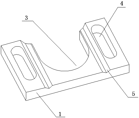
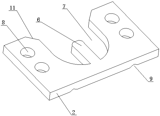
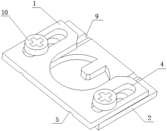
[0015] Such as Figure 1 to Figure 3 As shown, a clamp for fixing an optical cable strength member includes a rectangular upper clamp 1 and a lower clamp 2, the upper clamp and the lower clamp have the same length and width and are placed in reverse. There is a "U"-shaped mouth-3 in the middle of the long side of the upper fixture 1, and a chute 4 is provided on both sides of the "U"-shaped mouth-3, and a "V" is opened between the chute 4 and the "U"-shaped mouth-3. "shaped groove-5; chute 4 is convenient for the upper and lower clamps to fix the metal fixing parts in the optical cable joint box and fiber distribution box, and is suitable for metal fixing columns of different sizes.
[0016] In the middle of the long side on one side of the lower fixture 2, there is a "U" shaped mouth 2 7 that is the same size as the "U" shaped mouth 1 3, and the two sides of the "U" shaped mouth 7 are provided with screw holes 8. Preferably, there are two holes on each side. There are two sc...
Embodiment 2
[0022] Such as figure 1 , figure 2 and Figure 4 As shown, a clamp for fixing an optical cable strength member includes a rectangular upper clamp 1 and a lower clamp 2, the upper clamp and the lower clamp have the same length and width and are placed in the same direction. There is a "U"-shaped mouth-3 in the middle of the long side of the upper fixture 1, and a chute 4 is provided on both sides of the "U"-shaped mouth-3, and a "V" is opened between the chute 4 and the "U"-shaped mouth-3. " shaped groove one 5; the middle of the long side on one side of the lower fixture 2 has a "U" shaped mouth two 7 of the same size as the "U" shaped mouth one 3, and two sides of the "U" shaped mouth two 7 are provided with screw holes 8, Preferably there are two screw holes on each side, wherein the length of the chute 4 is greater than the longest connecting line between the two screw holes 8 . There is a fixed shaft core 6 in the middle of the "U"-shaped mouth 2 7, which is used to fi...
PUM
 Abstract
Description
Claims
Application Information
 - R&D
- Intellectual Property
- Life Sciences
- Materials
- Tech Scout
- Unparalleled Data Quality
- Higher Quality Content
- 60% Fewer Hallucinations
Browse by: Latest US Patents, China's latest patents, Technical Efficacy Thesaurus, Application Domain, Technology Topic, Popular Technical Reports.
© 2025 PatSnap. All rights reserved.Legal|Privacy policy|Modern Slavery Act Transparency Statement|Sitemap|About US| Contact US: help@patsnap.com


