
Cambered surface lens and manufacturing method thereof

A manufacturing method and curved surface technology, applied in the direction of instruments, electrical digital data processing, data processing input/output process, etc., can solve the problems of high overall cost, inability to achieve mass production, easily damaged touch sensing units, etc., and achieve reduction The effect of force, high strength and cost reduction

Active Publication Date: 2015-09-09
SHANTOU GOWORLD DISPLAY TECH CO LTD
View PDF2 Cites 6 Cited by
  • Summary
  • Abstract
  • Description
  • Claims
  • Application Information

AI Technical Summary

Problems solved by technology

[0005] At present, the general process of batch production of touch screens is: to make multiple touch sensing units on a large flat substrate, and then separate them to form a single touch screen, so as to realize the mass production of touch screens. If the edge of a single touch screen after mass production is polished into an arc However, if the edge of a single flat substrate is polished into a curved surface first, and then the touch sensing unit is manufactured, it is obvious that it can only be manufactured individually, and mass production cannot be realized.
[0006] Therefore, the display of this touch display screen with curved lenses needs to adopt a higher price embedded touch display (that is, a display integrated with a touch function), which has led to this touch display with curved lenses. The overall cost of the screen is higher

Method used


Image

  • Cambered surface lens and manufacturing method thereof
  • Cambered surface lens and manufacturing method thereof
  • Cambered surface lens and manufacturing method thereof

Examples


Embodiment Construction

[0031] Further description will be given below in conjunction with the accompanying drawings and preferred embodiments of the present invention.

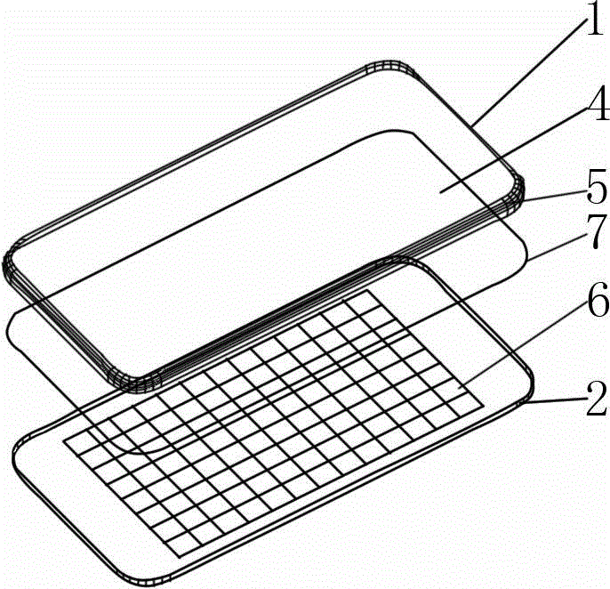
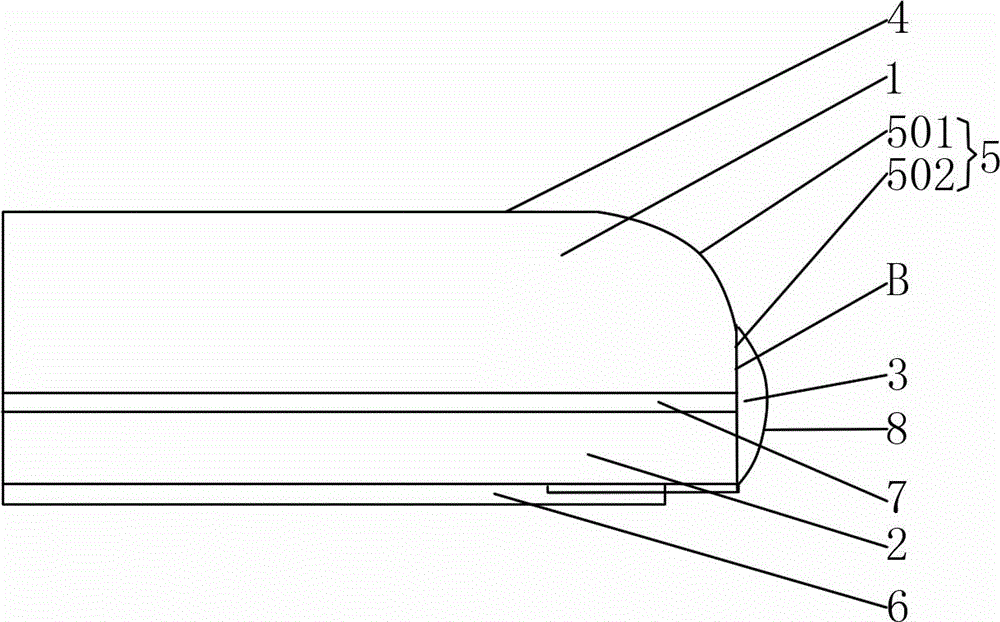
[0032] Such as figure 2 and image 3 As shown, this curved lens includes a first substrate 1, a second substrate 2 and an edge adhesive layer 3, the thickness of the first substrate 1 is 1.0mm (0.7-1.5mm is acceptable), and the thickness of the second substrate 2 is 0.5mm (0.3-0.7mm is acceptable); the inner surface of the first substrate 1 is a plane, and the outer surface of the first substrate 1 includes a middle plane 4 in the middle and an edge arc surface 5 in the periphery; the second substrate 2 is A planar substrate, the inner surface of the second substrate 2 is provided with a touch sensing circuit layer 6; the first substrate 1 has a first profile, the second substrate 2 has a second profile, and the deviation between the first profile and the second profile is 50 microns ( The deviation is less than 200 microns, and ...


PUM


Abstract

The invention relates to a cambered surface lens which comprises a first substrate and a second substrate. The inner side surface of the first substrate is a plane, the outer side surface of the first substrate comprises a middle plane and an edge cambered surface, the second substrate is a plane substrate, a touch induction circuit layer is arranged on the inner side surface of the second substrate, and the outer side surface of the second substrate is attached on the inner side surface of the first substrate through a transparent adhesive layer. As the cambered surface lens is set into a double-layer structure, the edge of the second substrate does not need to be polished into a cambered surface, the second substrate can be a transparent plate with fine impact resistance, a joint between the cambered surface lens and a shell can have high strength, the impact applied on the surface of the cambered surface lens can be buffered by the transparent adhesive layer, the stress at the joint between the cambered surface lens and the shell is reduced, and the cambered surface lens has fine impact resistance. As the second substrate is the plane substrate, the touch induction circuit layer is set according to an existing process, a common flat display instead of an embedded touch display can be selected, and cost is reduced.

Description

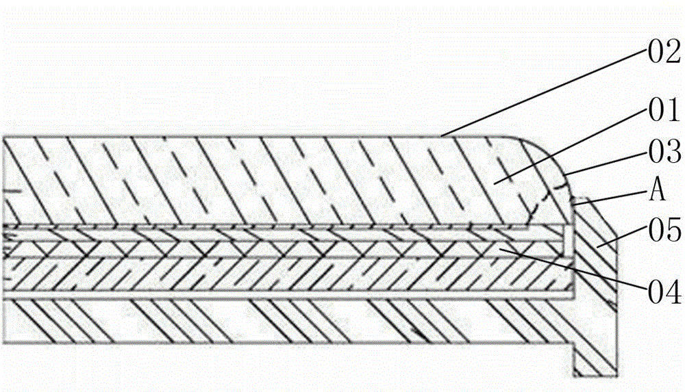
technical field [0001] The invention relates to the field of touch display, in particular to a curved lens for a touch display and a manufacturing method thereof. Background technique [0002] At present, some electronic products (mainly mobile phones) with 2.5D curved screens appear on the market. The touch control display screen of this 2.5D curved screen is a curved lens, such as figure 1 As shown, the surface of the curved lens 01 includes a middle plane 02 in the middle, and an edge curved surface 03 at the periphery. Since the periphery is a curved surface, it is more beautiful. On the periphery of the curved lens 01, the edge curved surface 03 can also The black border of the display is hidden through a certain refractive effect to achieve a visual borderless effect. [0003] At present, such a touch display screen with a curved lens generally includes a flat panel display 04 and a curved lens 01, the curved lens 01 is attached to the outer surface of the flat panel ...

Claims


Application Information

Patent Timeline
Patent Type & Authority Applications(China)
IPC IPC(8): G06F3/041
Inventor 吴永俊沈奕林钢朱世健吕岳敏张汉焱余荣孙楹煌杜训新
Owner SHANTOU GOWORLD DISPLAY TECH CO LTD
Learn More