
Magnetic lifting handle for assembling ferromagnetic precision workpieces

A technology of magnetic force and magnetic base, applied in the direction of electrical components, manufacturing tools, hand-held tools, etc., can solve the problems of no convenient extraction, moving handles or hooks, etc., achieve convenience, reliability, no scratches, improve assembly efficiency, practical and convenient Effect

Inactive Publication Date: 2015-09-09
CHINA ELECTRIC POWER RES INST +1
View PDF8 Cites 4 Cited by
  • Summary
  • Abstract
  • Description
  • Claims
  • Application Information

AI Technical Summary

Problems solved by technology

At the same time, there are strict technical requirements for the installation of the magnetic core. The upper and lower multi-layer magnetic cores must be strictly positioned. Through special tooling, the installation depends on the manual alignment of the staff. The magnetic core is cylindrical after casting, and there is no handle for easy extraction and movement. Or hooks, and the surface of the magnetic core must be strictly protected without any damage, so a tool for extracting, moving and installing the magnetic core is urgently needed

Method used


Image

  • Magnetic lifting handle for assembling ferromagnetic precision workpieces
  • Magnetic lifting handle for assembling ferromagnetic precision workpieces
  • Magnetic lifting handle for assembling ferromagnetic precision workpieces

Examples


Embodiment Construction

[0026] In order to make the object, technical solution and advantages of the present invention clearer, the present invention will be further described in detail below in conjunction with the accompanying drawings and embodiments. It should be understood that the specific embodiments described here are only used to explain the present invention, not to limit the present invention. In addition, the technical features involved in the various embodiments of the present invention described below can be combined with each other as long as they do not constitute a conflict with each other.

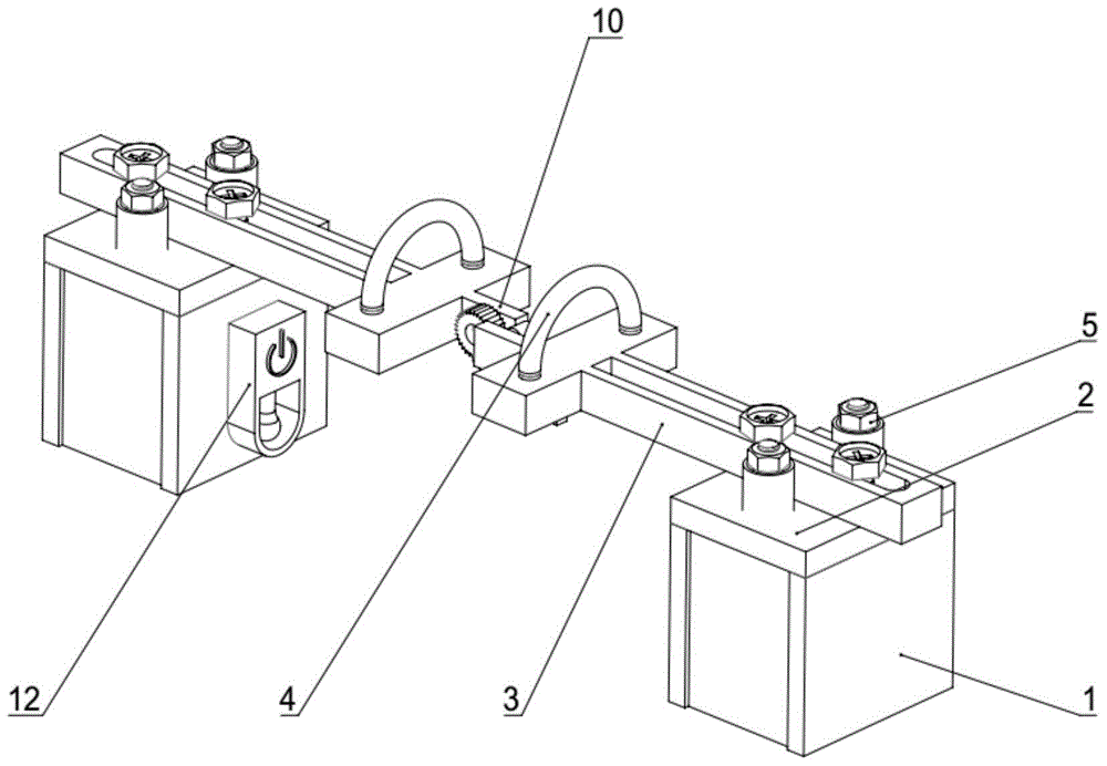
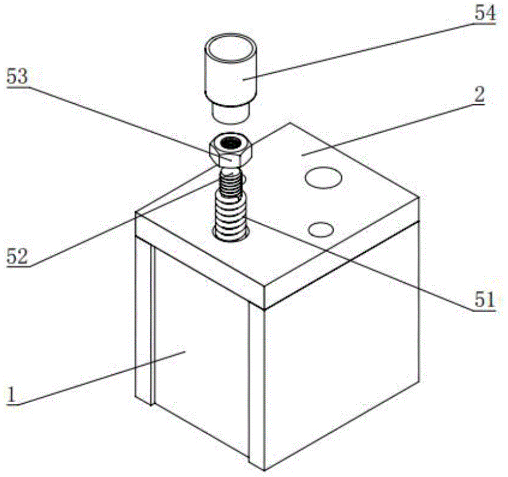
[0027] refer to figure 1 , The magnetic handle of the present invention includes two magnetic actuators and a rotation adjustment mechanism. The magnetic actuator includes a magnetic base 1, an intermediate connecting plate 2, a bearing arm 3, a handle 4 and an elastic positioning mechanism 5; the upper end surface of the magnetic base 1 is fixedly connected to the bearing arm 3 through an inte...


PUM


Abstract

The invention relates to a magnetic lifting handle, in particular to a magnetic lifting handle for assembling ferromagnetic precision workpieces. The magnetic lifting handle comprises two magnetic actuating mechanisms and rotating adjustment mechanisms connected between the two magnetic actuating mechanisms, each magnetic actuating mechanism comprises a magnetic seat, a middle connecting plate, a force bearing arm, an elastic positioning mechanism and a handle, the upper end faces of the magnetic seat are fixedly connected with the force bearing arms through the middle connecting plates, through holes are formed in the middle connecting plates, the elastic positioning mechanisms connected with the upper end faces of the magnetic seats are arranged in the through holes, one end of each force bearing arm is connected with one side of the corresponding handle, a connecting arm for connecting the corresponding rotating adjustment mechanism is arranged on the other side of the handle, each rotating adjustment mechanism comprises a ratchet, a pawl, a rotating shaft and a spring, the ratchets are fixed on the connecting arm of one magnetic actuating mechanism, rotating ends of the pawls are connected with the connecting arm of the other magnetic actuating mechanism through the rotating shafts, and large ends of the pawls are connected with the handle of the other magnetic actuating mechanism through the springs. The magnetic lifting handle is simple in structure, convenient to use, stable and reliable, and the precision ferromagnetic workpieces can be assembled without being scratched and stained.

Description

technical field [0001] The invention belongs to the technical field of magnetic workpiece assembly, and in particular relates to a magnetic handle used for assembling ferromagnetic precision workpieces. Background technique [0002] The electron irradiation accelerator is one of the key equipments in the irradiation processing industry. It irradiates the irradiated substance by generating an electron beam with a certain energy and intensity, and causes the physical and chemical changes of the substance through the interaction between the electron beam and the substance. , biological and other effects, in order to achieve a series of application purposes such as material modification, coating curing, disinfection and sterilization, and environmental protection. The irradiation industry is an industry with high social and economic benefits and broad development prospects. The most critical component in the electron irradiation accelerator system is the high-power DC high-volt...

Claims


Application Information

Patent Timeline
Patent Type & Authority Applications(China)
IPC IPC(8): H01F41/02B25B27/00
Inventor 杨波杨军鄢盛驰梅志远冯鑫振左晨刘欢周晨李远鹏李梦奎刘旭
Owner CHINA ELECTRIC POWER RES INST
Learn More