
Trailer box with brake anti-rotation

An anti-rotation and action technology, applied in the field of luggage, can solve the problem of unbalanced force, such as the car spinning, and achieve the effect of balanced braking force

Inactive Publication Date: 2016-06-01
田爱红
View PDF5 Cites 0 Cited by
  • Summary
  • Abstract
  • Description
  • Claims
  • Application Information

AI Technical Summary

Problems solved by technology

[0004] In order to overcome the deficiencies in the prior art, one of the purposes of this application is to control the speed of the trolley when going downhill; the second purpose of this application is to solve the problem of unbalanced car spinning when braking

Method used


Image

  • Trailer box with brake anti-rotation
  • Trailer box with brake anti-rotation
  • Trailer box with brake anti-rotation

Examples


Embodiment 1

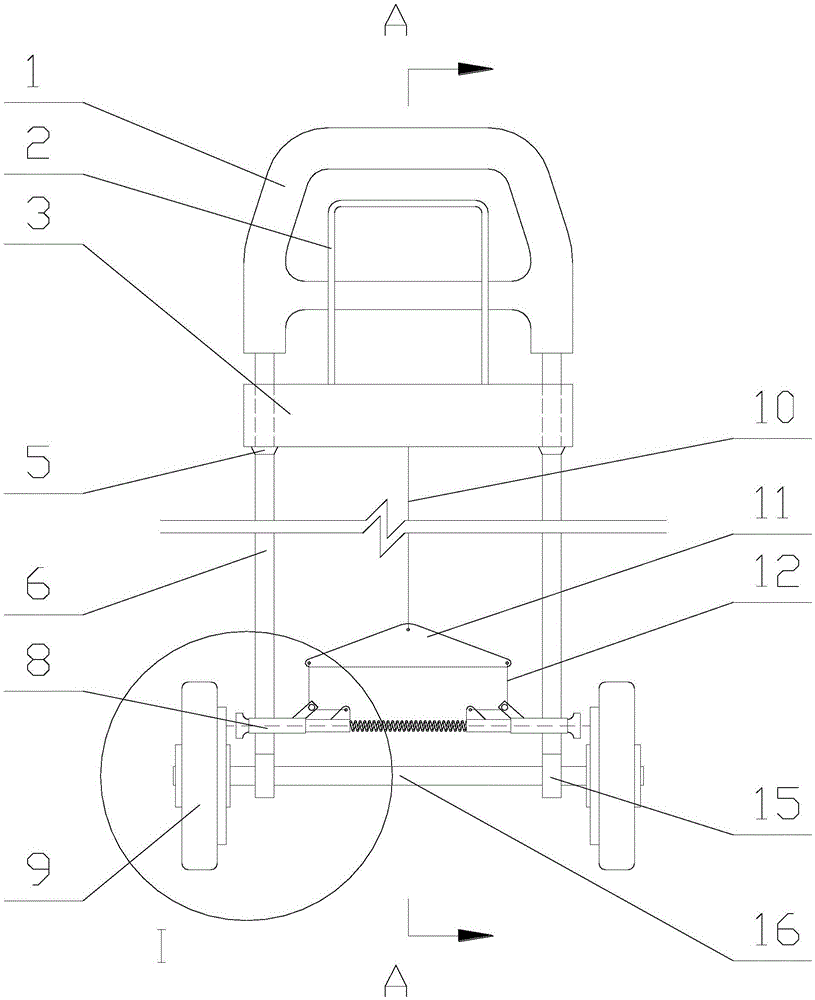
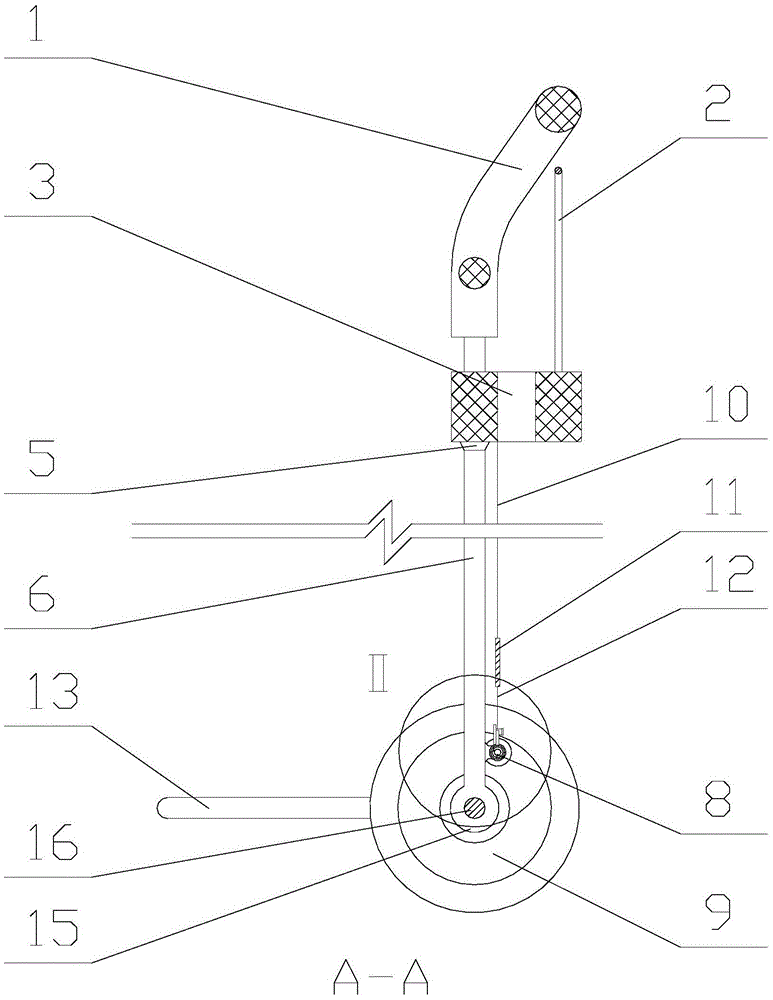
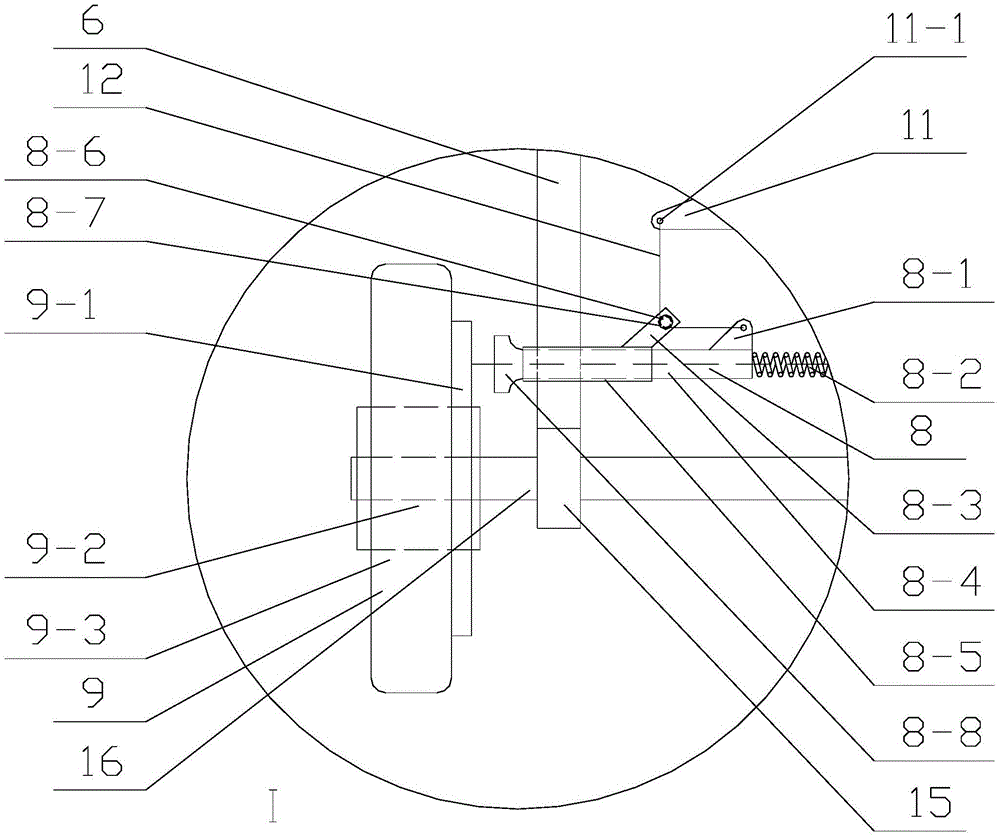
[0045] 1. The drag box with brake anti-rotation function, including: pull rod handle 1, brake handle 2, sliding device 3, sliding device stop 5, pull rod 6, braking device 8, wheel assembly 9, central brake cable 10, Brake force equalizer bar 11, brake cable hole 11-1, side wing brake cable 12, support frame 13, pull rod bushing 15, wheel axle rod 16;

[0046] It is characterized by:

[0047] The braking device 8 is two groups of left and right symmetry, and the braking device 8 includes: a brake cable connection seat 8-1, a return spring 8-2, a guide shaft support 8-3, a brake shoe pillar 8-4, and a pillar sleeve 8-5, brake cable guide shaft 8-6, brake cable stopper 8-7, brake shoe 8-8;

[0048] The wheel assembly 9 is also two groups of left and right symmetry, including: brake disc 9-1, wheel bearing 9-2, wheel body 9-3;

[0049] The pull rod handle 1 is on the top of the pull rod 6, the upper part of one end of the sliding device 3 is connected to the brake handle 2 and ...

Embodiment 2

[0073] 1. The drag box with brake anti-rotation function, including: pull rod handle 1, brake handle 2, sliding device 3, sliding device stop 5, pull rod 6, braking device 8, wheel assembly 9, central brake cable 10, Brake force equalizer bar 11, brake cable hole 11-1, side wing brake cable 12, support frame 13, pull rod bushing 15, wheel shaft rod 16;

[0074] It is characterized by:

[0075] The braking device 8 is two groups of left and right symmetry, and the braking device 8 includes: a brake cable connection seat 8-1, a return spring 8-2, a guide shaft support 8-3, a brake shoe pillar 8-4, and a pillar sleeve 8-5, brake cable guide shaft 8-6, brake cable stopper 8-7, brake shoe 8-8;

[0076] The wheel assembly 9 is also two groups of left and right symmetry, including: brake disc 9-1, wheel bearing 9-2, wheel body 9-3;

[0077] The pull rod handle 1 is on the top of the pull rod 6, the upper part of one end of the sliding device 3 is connected to the brake handle 2 and...


PUM


Abstract

The invention discloses a dragging tank with a brake anti-rotation function, and relates to the technical field of trunks. The dragging tank is characterized in that a pull rod handle is arranged at the top of a pull rod; the upper part of one end of a sliding device is connected with the other end of a brake handle, sleeves the pull rod, and is in sliding connection with the pull rod; the sliding device is connected with a center brake rope; a braking force balance rod is in an isosceles triangle; a brake rope hole in a triangular vertex angle of the braking force balance rod is connected with the center brake rope; brake rope holes in two base angles are connected with two flank brake ropes; the two flank brake ropes come round a brake rope guide shaft and are connected with a brake rope connection base; the outer wall of a support column sleeve is connected with the pull rod; brake shoe support columns are arranged in the support column sleeve; the outer sides of the brake shoe support columns are connected with the brake shoe; the inner sides of two groups of brake shoe support columns are connected with reset springs; the upper part of the inner side of the outer wall of the support column sleeve is connected with a guide shaft bracket; a wheel body is connected with a wheel bearing; and the wheel bearing is connected with a wheel axle rod. The dragging tank with the brake anti-rotation function is capable of controlling the speed of a pull rod vehicle when running downhill, and preventing people from slipping along with the vehicle when descending the slope to cause trample.

Description

technical field [0001] The utility model relates to a trailer box with a brake anti-rotation function, which relates to the technical field of luggage boxes. Background technique [0002] In real life, people often carry trolley bags when traveling, traveling, and visiting relatives and friends due to unfamiliar roads, and they often carry trolley bags when going to markets and visiting supermarkets. Stations, docks and other places have to pass through tunnels and overpasses, so it is inevitable to go up and down ramps. However, no matter whether the trolley case or the trolley bag is dragged down the ramp, people often cannot hold the luggage with them because the luggage is too heavy. Sliding down, faster and faster out of control. [0003] Chinese patent 201120286004.2, although it has the effect of adapting to the height of the user and can change the length of the pull bar, yet this patent only discloses such words "the wheel brake that can make the roller 4 slow down...

Claims


Application Information

Patent Timeline
Patent Type & Authority Patents(China)
IPC IPC(8): A45C5/14A45C13/00
Inventor 马宏
Owner 田爱红
Learn More