Force measuring and supporting structure

A support structure and force measurement technology, which is applied in diagnostic recording/measurement, medical science, sports accessories, etc., can solve problems such as single structure, complex circuit design, and insufficient reliability, and achieve high bearing capacity, strong practicability, and structural simple and reliable effect

Inactive Publication Date: 2015-09-16
CHINA NORTH VEHICLE RES INST
View PDF5 Cites 21 Cited by
  • Summary
  • Abstract
  • Description
  • Claims
  • Application Information

AI Technical Summary

Problems solved by technology

The existing plantar force measurement equipment has a single structure, the force measurement method is mostly directly measured by the force...

Method used


Image

  • Force measuring and supporting structure
  • Force measuring and supporting structure
  • Force measuring and supporting structure

Examples


Embodiment

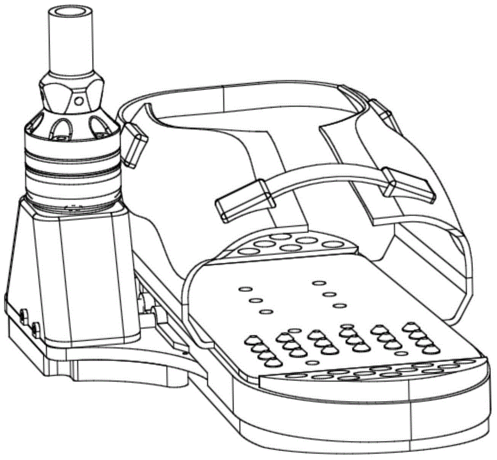
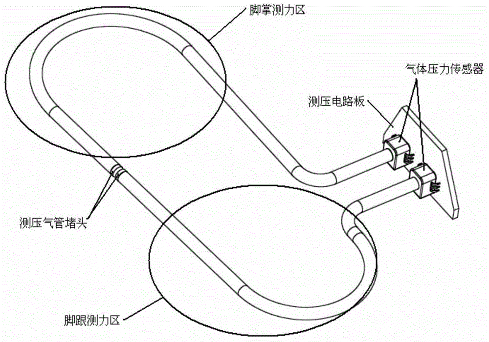
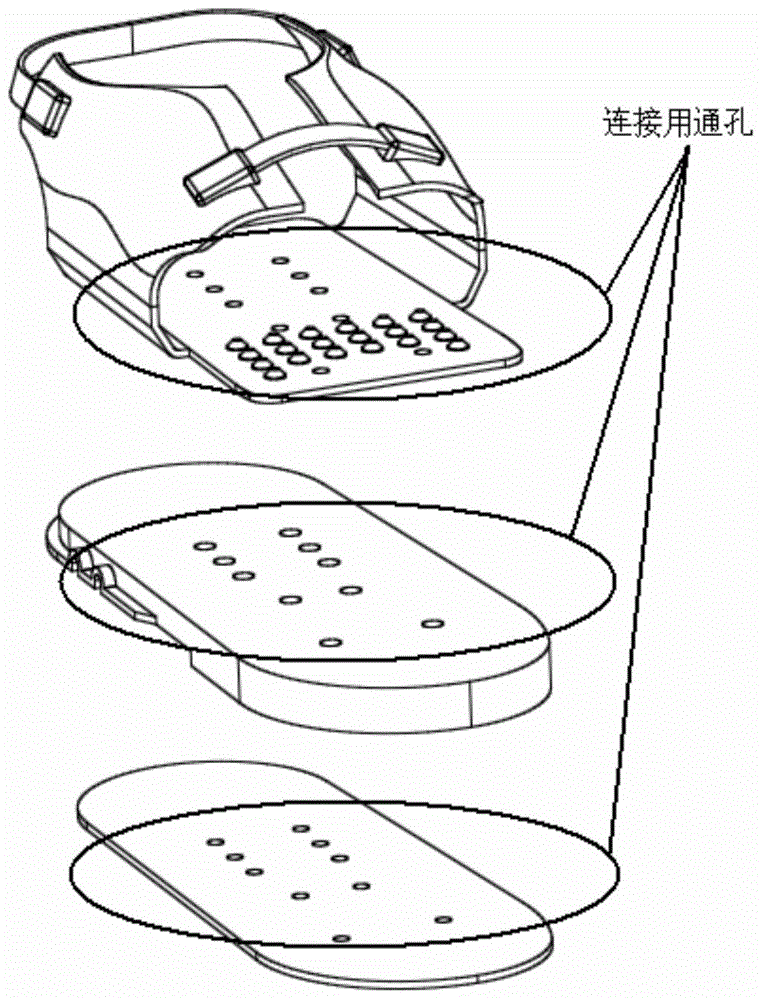
[0060] This embodiment provides a force measurement and support structure, which consists of the following parts, such as Figure 11 (right foot part) as shown: shoe cover 1, heel buffer rubber pad 2, sole buffer rubber pad 3, sensor cover 4, pressure measuring tube insole 5, heel pressure measuring air tube 6, sole pressure measuring air tube 7, Juyaan Fat shaping pad 8, trachea shaping pad 9, metal support plate 10, bottom pad 11, support body rubber pad 12, pressure measuring circuit board 13, ankle support body 14, ankle joint fixing head 15, ankle joint buffer lower gasket 16 , Ankle joint buffer 17, pad 18 on the ankle joint buffer, ball joint fixing ring 19, ball joint 20, ball joint socket 21, calf connector 22.

[0061] The wearer can wear the dynamometer and support structure (left foot portion and right foot portion) while wearing the shoe normally. When wearing, first loosen the buckle of the shoe cover 1, open the two-wing structure, put the foot into the shoe co...


PUM


Abstract

The invention belongs to the technical field of a human body mechanics design, and specifically relates to a force measuring and supporting structure, for measuring stress change conditions of a front sole and a rear sole at the bottom of a human foot and supporting a matched device. Compared to the prior art, plantar stress is converted into change of air pressure in an air pipe, a force measuring effect is achieved through acquisition of gas pressure, the structure is simple and reliable, supporting of the matched device above an ankle joint and buffering of a load impact are taken into full consideration, and the practicality is high. When a person moves, plantar pressure forces the pressure measuring air pipe to be compressed and deformed, the internal air pressure is changed, a gas pressure sensor converts pressure signals into electric signals, and a monitoring system can determine the change condition of the plantar pressure according to the signals; and the structure of the ankle joint guarantees a higher carrying capacity, and takes full consideration of a buffering effect caused by motion to a force.

Description

technical field [0001] The invention belongs to the technical field of human body mechanics design, and specifically relates to a force-measuring and supporting structure, which can be worn on the human foot, has good man-machine adaptability, and can measure the change of force on the front and rear soles of the human foot. And support other supporting equipment above the ankle joint. Background technique [0002] In human-powered exoskeleton and similar equipment, it is necessary to monitor the force on the user's foot to provide data support for the control system. The existing plantar force measurement equipment has a single structure, and the force measurement method is mostly directly measured by a force sensor. The force measurement device is bulky and the circuit design is complicated, which leads to insufficient reliability in practical application. Contents of the invention [0003] (1) Technical problems to be solved [0004] The technical problem to be solved...

Claims


Application Information

Patent Timeline
IPC IPC(8): A61B5/22A61B5/11
Inventor 金昊龙宋慧新王超侯友山陈宇马明徐广龙肖洁曹宇赵宁药凌宇房志军刘文英何军
Owner CHINA NORTH VEHICLE RES INST
Why Eureka
Try Eureka