Movable clamping device

A clamping device and side technology, which is applied in the field of mobile clamping devices, can solve the problems of insufficient length of the positioning mandrel, affecting the processing of parts under the tool, and the scrapping of parts, so as to improve the processing efficiency and product quality.

Active Publication Date: 2015-09-16
鹰普(中国)有限公司
View PDF6 Cites 7 Cited by
  • Summary
  • Abstract
  • Description
  • Claims
  • Application Information

AI Technical Summary

Problems solved by technology

[0002] The traditional clamping mechanism is generally used to clamping from the outside of the part, but for some parts with complex shapes and difficult processing, this positioning and clamping method not only increases the volume of the tooling, but also affects the On the other hand, this part is positioned with one pin on one side and two points on the side. Since the length of the positioning mandrel is not enough, if the force of the two points on the side to fix the direction of rotation of the part is too large, it may occur The state of pushing the part to the top, which will eventually lead to the scrapping of the part

Method used


Image

  • Movable clamping device
  • Movable clamping device
  • Movable clamping device

Examples


Embodiment Construction

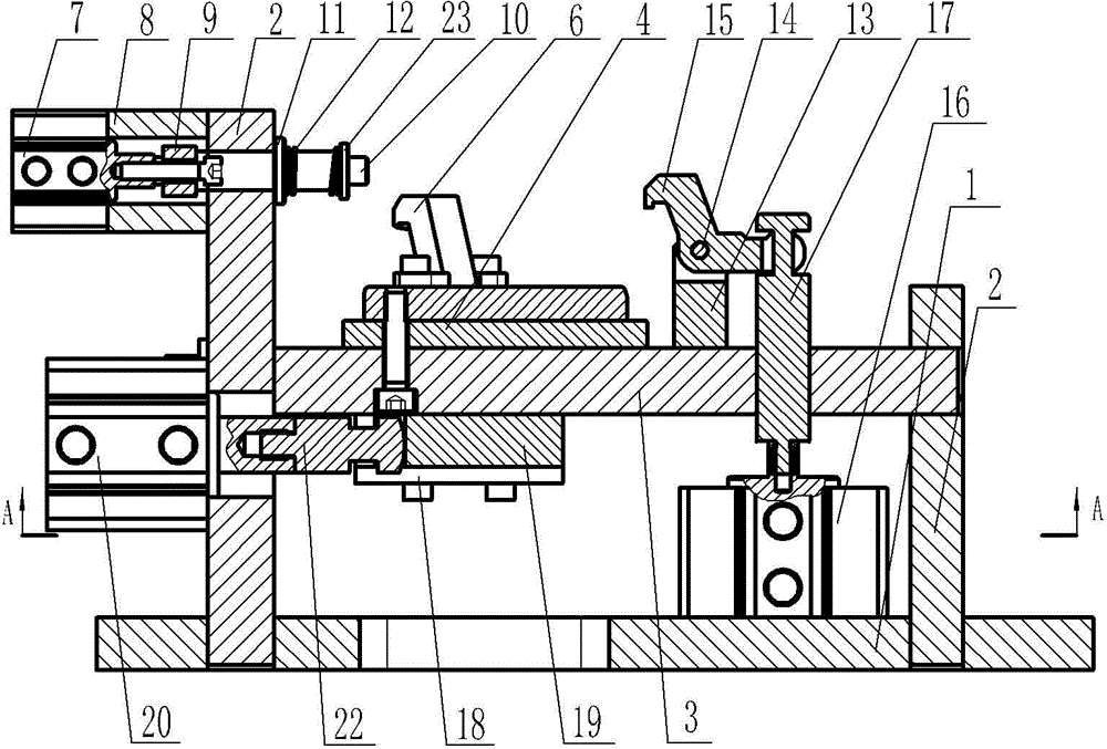
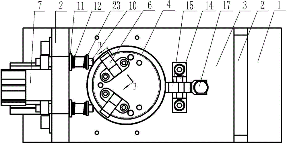
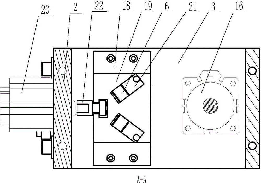
[0018] See figure 1 , figure 2 , image 3 , Figure 4 As shown, a mobile clamping device includes a base plate 1, side baffles 2 are respectively installed on both sides of the upper end surface of the base plate 1, a support plate 3 is installed between the two side baffles 2, and a support plate 3 is installed on the support plate 3. There is a cylindrical positioning seat 4, and a circular step is arranged on the cylindrical positioning seat 4, which can better realize the positioning of parts. Two through grooves are symmetrically opened on the cylindrical positioning seat and the support plate 4, and each through groove A reversible inner pressure plate 6 is installed through the first pin shaft 5, a guide seat 18 is installed at the lower end of the support plate 3, and a slidable slider 19 is installed on the guide seat 18, and one end of the slider 19 is connected to the horizontal pressure plate through the connector 22. To tighten the cylinder 20, the slider 19 h...


PUM


Abstract

The invention relates to the technical field of machining of precision castings, in particular to a movable clamping device. By the movable clamping device, parts can be positioned and clamped conveniently, and machining efficiency and product quality can be improved. The movable clamping device comprises a baseplate. Lateral stop plates are mounted on two sides of the upper end face of the baseplate respectively. A support plate is mounted between the two lateral stop plates. A cylindrical positioning base is mounted on the support plate. Through grooves are formed in the cylindrical positioning base and the support plate. Reversible inner press plates are mounted in the through grooves through first pins. A horizontal positioning air cylinder is mounted on the lateral stop plate on one side. A positioning head is mounted on a piston rod of the horizontal positioning air cylinder. A support base is mounted on the support plate on the lateral portion of the cylindrical positioning base. A reversible outer press plate is mounted on the support base through a second pin.

Description

technical field [0001] The invention relates to the technical field of precision casting machining, in particular to a mobile clamping device. Background technique [0002] The traditional clamping mechanism is generally used to clamping from the outside of the part, but for some parts with complex shapes and difficult processing, this positioning and clamping method not only increases the volume of the tooling, but also affects the On the other hand, this part is positioned with one pin on one side and two points on the side. Since the length of the positioning mandrel is not enough, if the force of the two points on the side to fix the direction of rotation of the part is too large, it may occur The state of pushing the part to the top will eventually lead to the scrapping of the part. Contents of the invention [0003] In order to solve the above problems, the present invention provides a mobile clamping device, which can conveniently realize positioning and clamping o...

Claims


Application Information

Patent Timeline
Patent Type & Authority Applications(China)
IPC IPC(8): B23Q3/08
CPCB23Q3/08B23Q2703/04
Inventor 朱国宏高娜
Owner 鹰普(中国)有限公司
Why Eureka
Try Eureka