Rear suspension assembly

A technology of rear suspension and rear suspension bracket, which is applied in the direction of power plant, jet propulsion device, internal combustion propulsion device, etc. It can solve the problems of low production efficiency, reduction of installation contact parts, unevenness, etc.

Active Publication Date: 2015-09-16
ANHUI JIANGHUAI AUTOMOBILE GRP CORP LTD
View PDF8 Cites 4 Cited by
  • Summary
  • Abstract
  • Description
  • Claims
  • Application Information

AI Technical Summary

Problems solved by technology

[0004] The above-mentioned rear suspension bracket has the following defects: one, because the rear suspension bracket and the rubber pad are on the same plane in the Y direction (under the vehicle coordinate system), on the one hand, in order to ensure that the engine with the rear suspension bracket is placed on the In the engine compartment, the installation contact part between the bracket and the rubber pad is greatly reduced, and the reduction of the contact area leads to an increase in the pressure on the rubber pad pressing block, which is uneven, and the vibration isolation and shock absorption performance of the rubber pad cannot be very good. First, the rubber pad and the rear suspension bracket are prone to fracture and failure, and the reliability is low; second, the Y-direction projection distance between the outer edge of the cantilever and the upper wing surface of the frame is almost zero. It is particularly difficult to hoist the powertrain, and the production efficiency is low; third, the mounting bolts of the rear suspension bracket and the engine are almost in contact with the rubber pads in the rear suspension rubber pad assembly, and there is a potential interference

Method used


Image

  • Rear suspension assembly
  • Rear suspension assembly
  • Rear suspension assembly

Examples


Embodiment Construction

[0051] In order to enable those skilled in the art to better understand the technical solutions of the present invention, the present invention will be further described in detail below in conjunction with the accompanying drawings.

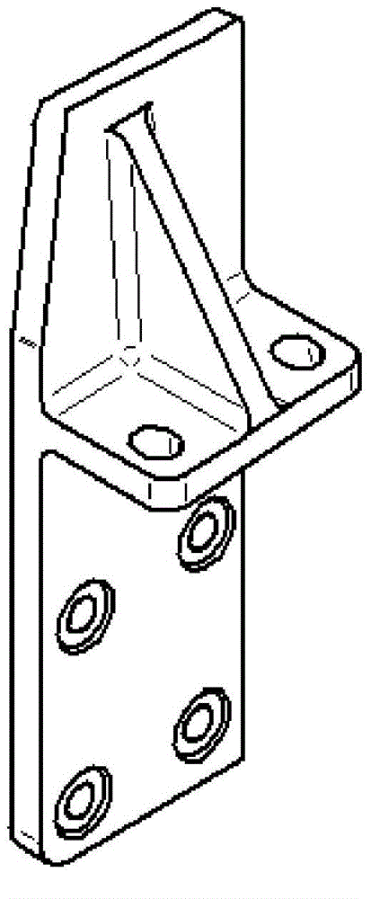
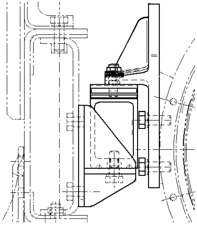
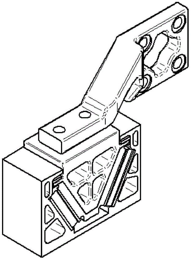
[0052] Such as Figure 3-24 As shown, the embodiment of the present invention provides a rear suspension assembly, which includes a rear suspension rubber pad assembly and a rear suspension bracket, and the rear suspension rubber pad assembly includes a rubber pad base, a rubber pad pressing block and a rubber pad . in:

[0053] The rear suspension bracket is connected between the engine and the rear suspension rubber pad assembly, which includes an engine fixing plate 11 for fixing to the flywheel housing of the engine, and a rubber pad fixing plate 12 for fixing to the rubber pad pressing block , The engine fixing plate 11 and the rubber pad fixing plate 12 are flat structures, and the extension surfaces of the two are perpendicular to each o...


PUM


Abstract

The invention discloses a rear suspension assembly. A rear suspension rubber pad comprises a rubber pad base, a rubber pad pressure block and a rubber pad. A rear suspension support comprises an engine fixation plate used for fixation to the flywheel housing of an engine and a rubber pad fixation plate used for fixation to the rubber pad pressure block. The engine fixation plate and the rubber pad fixation plate are each of a flat structure, the extending surfaces of the two are vertical, and the engine fixation plate and the rubber pad fixation plate are fixed along the length direction of a vehicle; the rubber pad pressure block comprises a pressure block body provided with an upper installation surface and rubber pad bonding surfaces, support ribs are fixed inside the pressure block body, and weight reduction holes are arranged at the two sides of the support ribs; and the rubber pad comprises two rubber pad bodies fixed to each other, and each rubber pad comprises at least two superposed bodies and liner plates fixed between two adjacent bodies. According to the invention, the rear suspension support can improve the reliability of the rear suspension assembly and the production efficiency of automobiles, and at the same time, interference generated between an installation bolt of the rear suspension support and an engine and the rubber pad can be prevented.

Description

technical field [0001] The invention relates to the technical field of automobile structures, in particular to a rear suspension assembly. Background technique [0002] In recent years, with the rapid expansion of the domestic automobile market, heavy trucks have also developed vigorously. Straight-through longitudinal beam frame is widely used in various types of heavy trucks. Although this kind of straight-through vertical beam frame has the advantages of simple molding, high production efficiency, high degree of generalization of structure and good reliability, etc., its open gear size is small, especially the engine mount, which is one of the engine and its accessories. Insufficient installation space has caused a lot of inconvenience and confusion to the design of the engine mount, affecting the reliability of the engine mount and reducing the production efficiency of the manufacturing company. [0003] At present, the suspension structure of heavy-duty trucks is main...

Claims


Application Information

Patent Timeline
Patent Type & Authority Applications(China)
IPC IPC(8): B60K5/12
Inventor 董金国王俊伟高艳军李海波惠周朋许芳王立立
Owner ANHUI JIANGHUAI AUTOMOBILE GRP CORP LTD
Why Eureka
Try Eureka