Vibrating table shock-absorbing foundation structure and its construction method

A technology of basic structure and construction method, which is applied in the field of test engineering, can solve the problems of small foundation quality, unsatisfactory, and hazards of surrounding workshops, and achieve the effect of exempting maintenance costs, reducing hazards, and increasing quality and rigidity

Active Publication Date: 2017-01-18
ZHUZHOU CSR TIMES ELECTRIC CO LTD
View PDF5 Cites 0 Cited by
  • Summary
  • Abstract
  • Description
  • Claims
  • Application Information

AI Technical Summary

Problems solved by technology

The air spring vibration isolation type foundation structure is simple and the foundation quality is small, but the air spring needs to be replaced every once in a while, and the vibration frequency is generally about 5Hz, which cannot meet the vibration test requirements of large rolling stock equipment starting from 2Hz
Since the reinforced concrete foundation is directly connected to the ground, it is easy to cause harm to the surrounding factory buildings during the vibration test. Since this foundation is made of concrete, it is difficult for its installation surface to meet the flatness and accuracy requirements of the vibration table installation.

Method used


Image

  • Vibrating table shock-absorbing foundation structure and its construction method
  • Vibrating table shock-absorbing foundation structure and its construction method
  • Vibrating table shock-absorbing foundation structure and its construction method

Examples


Embodiment Construction

[0080] In order to make the purpose, technical solutions and advantages of the embodiments of the present invention clearer, the technical solutions in the embodiments of the present invention will be clearly and completely described below in conjunction with the drawings in the embodiments of the present invention. Obviously, the described embodiments It is only some embodiments of the present invention, but not all embodiments. Based on the embodiments of the present invention, all other embodiments obtained by persons of ordinary skill in the art without creative efforts fall within the protection scope of the present invention.

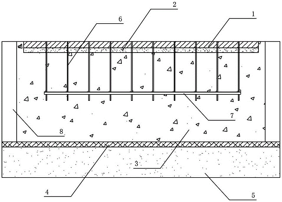
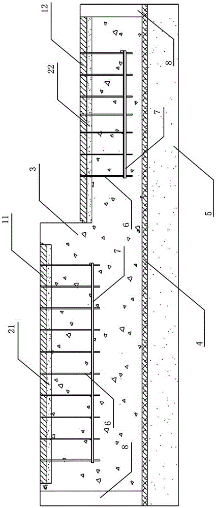
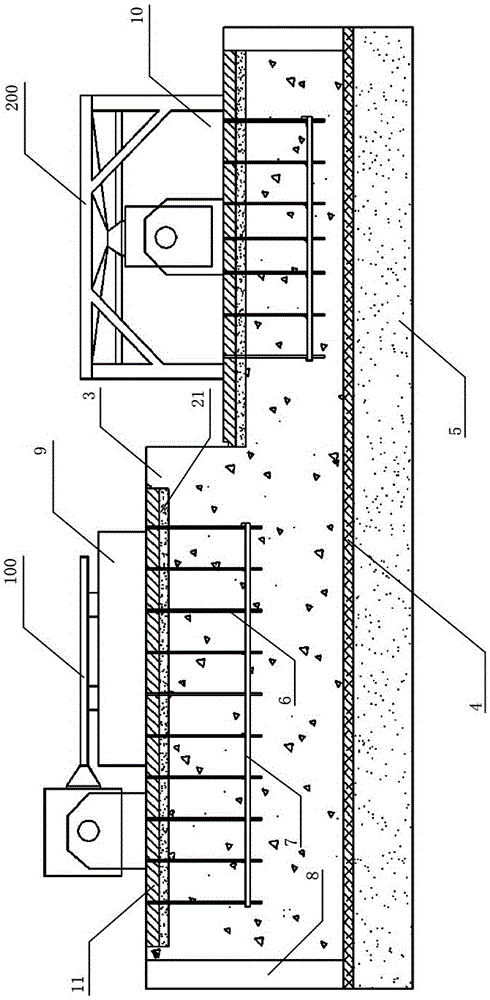
[0081] as attached figure 1 To attach Figure 14 As shown, the specific embodiments of the shock-absorbing foundation structure of the vibration table and the construction method thereof of the present invention are given, and the present invention will be further described below in conjunction with the accompanying drawings and specific embodime...


PUM


Abstract

The invention discloses a vibrating table vibration reducing foundation structure and a construction method thereof. The structure comprises a vibrating table mounting steel plate, an epoxy resin casting layer, a reinforcement concrete block body, a thin concrete cushion layer, a flexible object cushion layer, an embedded frame and a foundation bolt, wherein a horizontal and / or vertical vibrating table is arranged on the vibrating table mounting steel plate; the epoxy resin casting layer is positioned below the vibrating table mounting steel plate; the reinforcement concrete block body is positioned below the epoxy resin casting layer; the epoxy resin casting layer is used for bonding the vibrating table mounting steel plate with the reinforcement concrete block body; the thin concrete cushion layer is positioned below the reinforcement concrete block body; the flexible object cushion layer is positioned below the thin concrete cushion layer; the embedded frame is arranged in the reinforcement concrete block body; and the foundation bolt is used for connecting the embedded frame with the vibrating table mounting steel plate. Another structure comprises a vibrating table mounting steel plate and an epoxy resin casting layer positioned in different two heights and respectively used for mounting horizontal and vertical vibrating tables. The structure can effectively reduce the harm of vibration tests to surrounding factory buildings and environments, saves the maintenance cost, and can realize special technical requirement of vibration starting with lower frequency.

Description

technical field [0001] The invention relates to the field of test engineering, in particular to a large vibration table shock-absorbing foundation structure widely used in the fields of railway locomotives, automobiles, ships, aerospace, bridge construction, electronic communication and the like and a construction method thereof. Background technique [0002] The purpose of the vibration test is to verify that the designed product can withstand external or self-generated vibration without being damaged, and can exert its performance and reach the predetermined life. The vibration table is the key equipment for simulating the mechanical environment of the subject in actual work. It has been widely used in railway locomotives, automobiles, ships, aerospace, bridge construction, electronic communications and other fields. Therefore, in order to make the large-scale vibrating table reach a good technical state and reduce the damage to the surrounding factory buildings and the en...

Claims


Application Information

Patent Timeline
Patent Type & Authority Patents(China)
IPC IPC(8): E02D27/44E02D31/08
Inventor 王鹏余锋刘国涛张祥珊
Owner ZHUZHOU CSR TIMES ELECTRIC CO LTD
Why Eureka
Try Eureka