EGR cooler cleaning method and cleaning apparatus

An EGR cooler and cleaning method technology, applied in the field of vehicles, can solve the problems affecting engine performance, carbon deposition and acid liquid cleaning, reducing the amount of exhaust gas recirculation, etc., to ensure performance, solve carbon deposition and corrosion problems, increase cost effect

Inactive Publication Date: 2015-09-16
WEICHAI POWER CO LTD
View PDF5 Cites 10 Cited by
  • Summary
  • Abstract
  • Description
  • Claims
  • Application Information

AI Technical Summary

Problems solved by technology

[0009] The material upgrade adopted in option 1 will inevitably increase the cost of the EGR system, thereby reducing the competitiveness of the product
Moreover, this method does not clean up the carbon deposits and acid liquid in the EGR system, and cannot fundamentally solve the problems of carbon deposits and corrosion in the EGR syste

Method used


Image

  • EGR cooler cleaning method and cleaning apparatus
  • EGR cooler cleaning method and cleaning apparatus
  • EGR cooler cleaning method and cleaning apparatus

Examples


Embodiment Construction

[0037] The core of the present invention is to provide a cleaning method and device for an EGR cooler. The device and method can effectively solve the problems of carbon deposition and corrosion of the EGR cooler without increasing the system cost. The present embodiment will be described in detail below in conjunction with the accompanying drawings.

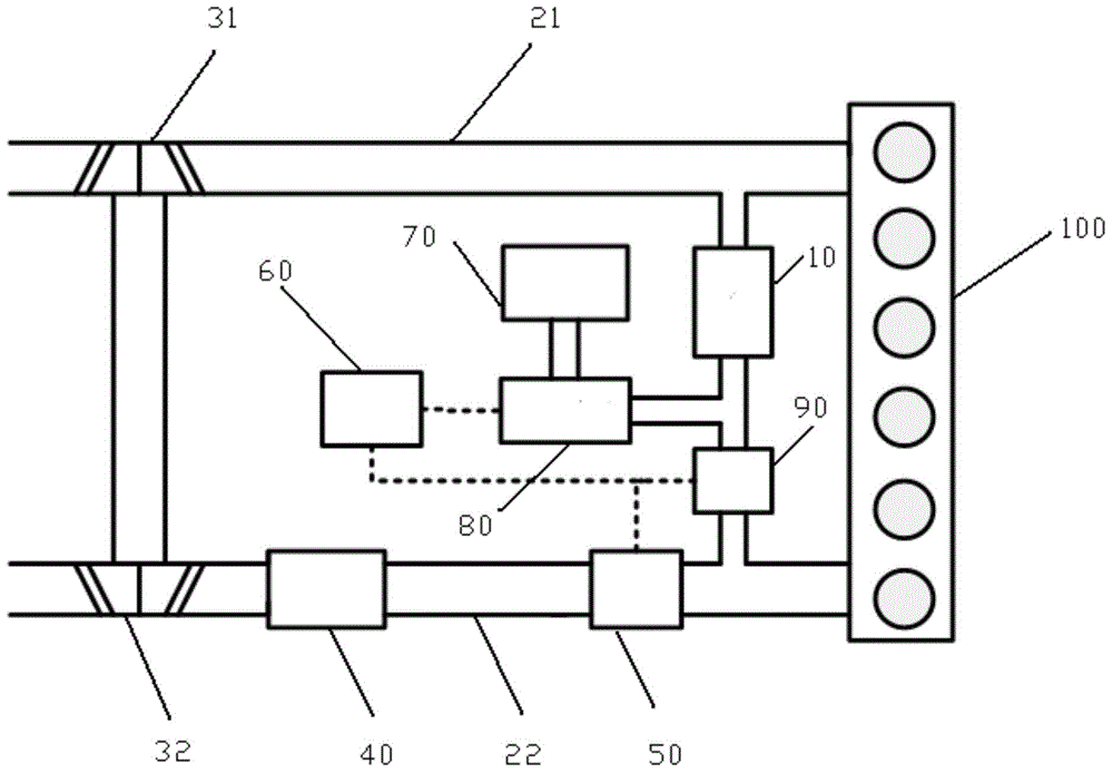
[0038] Please refer to figure 1 , figure 1 It is a structural schematic diagram of Embodiment 1 of the EGR cooler cleaning device provided by the present invention.

[0039] The cleaning device of the EGR cooler 10 in this embodiment includes a high-pressure gas source and an on-off valve 80, and the high-pressure gas source can communicate with the EGR cooler 10 through the on-off valve 80; it also includes a control on-off valve 80. control module. Here, the control module can be specifically integrated into the engine 100 control unit ECU60 of the vehicle, without a separate control unit, which saves the installation space...


PUM


Abstract

The invention discloses an EGR cooler cleaning method and cleaning apparatus. The cleaning method comprises the following steps of building an activation condition for EGR cooler cleaning, injecting high pressure air into the EGR cooler upon activation condition establishment to clean the EGR cooler. Substance such as carbon deposit and acid liquor are blown away via the high pressure airflows, so carbon deposit and corrosion can be prevented and performance of the EGR cooler can be ensured; and compared with the prior art, with material improvements and DOC arrangement, cost can be remained the same or reduced.

Description

technical field [0001] The invention relates to the technical field of vehicles, in particular to a cleaning method and a cleaning device for an EGR cooler. Background technique [0002] With the upgrading of emission regulations, the regulations require lower and lower limits for NOx in engine exhaust gas. Exhaust gas recirculation (EGR), as an effective measure to reduce engine NOx emission level, is more and more widely used in diesel engines. The EGR system includes an EGR cooler, an EGR valve and corresponding connecting pipelines. With the gradual wide application of EGR technology, a series of problems in the use of EGR system have become increasingly prominent. One of the most frequent problems is the carbon deposition and corrosion of the EGR cooler. [0003] As the usage time of the EGR cooler increases, the carbon deposits in the EGR cooler will gradually increase, which not only causes a decrease in the cooling efficiency of the EGR cooler, but also increases ...

Claims


Application Information

Patent Timeline
IPC IPC(8): F02B77/04F02M25/07
CPCY02T10/12
Inventor 李峰栾军山姚旺张广西南宁宁
Owner WEICHAI POWER CO LTD
Why Eureka
Try Eureka