Air compression device and air compressor

A technology of air compression and cylinder, which is applied in the direction of pump devices, mechanical equipment, machines/engines, etc., can solve the problems of poor air compression effect and poor effect, and achieve the goal of improving inflation work efficiency, good compression effect and prolonging service life Effect

Active Publication Date: 2015-09-16
ZHEJIANG SHENYUAN ELECTRO MACHINERY
View PDF10 Cites 8 Cited by
  • Summary
  • Abstract
  • Description
  • Claims
  • Application Information

AI Technical Summary

Problems solved by technology

Most air compressor chambers adopt the reciprocating piston type. The compression element is a piston, which reciprocates in the cylinder to compress the air. The piston and cylinder structure adopts the exist

Method used


Image

  • Air compression device and air compressor
  • Air compression device and air compressor
  • Air compression device and air compressor

Examples


Embodiment Construction

[0027] The following are specific embodiments of the present invention and in conjunction with the accompanying drawings, the technical solutions of the present invention are further described, but the present invention is not limited to these embodiments.

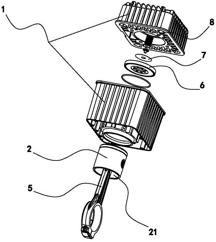
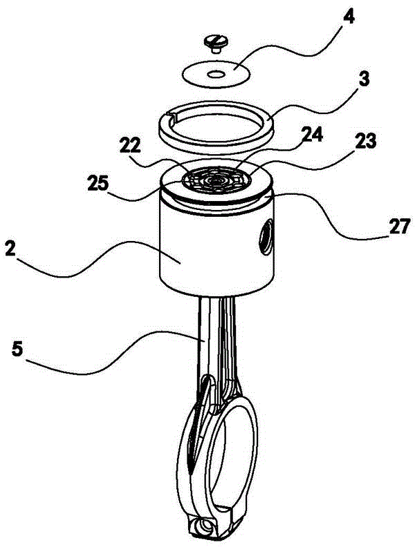
[0028] Such as figure 1 , 2 , 3, 4, 5, 6 and 7, the air compression device includes a cylinder 1 and a piston 2 and a piston rod 5 installed in the cylinder 1, the cylinder 1 has an air inlet and an air outlet, and the inner cavity 21 of the piston 2 is the air inlet. The cavity 21 of the piston 2 is provided with a connecting rod 26, one end of the above-mentioned piston rod 5 is sleeved on the connecting rod 26 and can swing around the connecting rod 26, and the other end is fixedly connected to the crank 11, and the crank 11 rotates under the drive of the motor 9 , thereby driving the piston rod 5 to reciprocate up and down, the piston 2 reciprocates up and down along the inner cavity wall of the cylinder 1 so that th...


PUM


Abstract

The invention provides an air compression device and an air compressor, pertaining to the technical field of air compression with the purpose of solving the problem that a conventional air compressor has poor compression effect. The air compression device comprises an air cylinder, a piston and a piston rod. The piston and the piston rod are arranged in the air cylinder. The air cylinder is provided with an air inlet and an air outlet. The piston has an inner cavity, in which a connecting rod is arranged. One end of the piston rod is arranged onto the connecting rod in a sleeving mode. The lower end of the piston is provided with an opening, in which multiple air inlet holes are formed. The air inlet holes are communicated with the air inlet by means of the inner cavity and the opening at the lower end. A diaphragm leaf base is arranged in the air cylinder. The upper end of the piston is provided with an air inlet diaphragm leaf enabling the air inlet holes to be sealed with or communicated with an above compression cavity. The upper end of the diaphragm leaf base is provided with multiple air outlet holes enabling the above compression cavity to be communicated with the air outlet of the air cylinder. The upper end of the diaphragm leaf base is provided with an air outlet diaphragm leaf. The air compression device is advantaged by being fine in air compression effect, high in efficiency and long in service lifetime.

Description

technical field [0001] The invention belongs to the technical field of air compression, and relates to an air compression device and an air compressor. Background technique [0002] At present, there are many types of air compressors, such as piston compressors, rotary compressors, and vane compressors. Most air compressor chambers adopt the reciprocating piston type. The compression element is a piston, which reciprocates in the cylinder to compress the air. The piston and cylinder structure adopts the existing common cylinder piston structure. The existing problems are: The existing common cylinder-piston structure is not effective when entering and exiting air, so that the air compression effect is not good. Contents of the invention [0003] The object of the present invention is to propose an air compression device for compressing air with high efficiency and high effect in view of the above-mentioned problems in the prior art. [0004] The purpose of the present in...

Claims


Application Information

Patent Timeline
IPC IPC(8): F04B39/10F04B41/06
Inventor 王友顺
Owner ZHEJIANG SHENYUAN ELECTRO MACHINERY
Why Eureka
Try Eureka