
Backlight module
A backlight module and light source assembly technology, which is applied in electric light sources, lighting devices, cooling/heating devices of lighting devices, etc., can solve problems such as poor heat conduction, and achieve the effect of simplifying the structure and facilitating thin design
- Summary
- Abstract
- Description
- Claims
- Application Information
AI Technical Summary
Problems solved by technology
Method used
Image

Examples
Embodiment Construction
[0023] Reference will now be made in detail to embodiments of the present invention, examples of which are illustrated in the accompanying drawings, wherein like numerals refer to like parts throughout. The embodiments are described below in order to explain the present invention by referring to the figures.
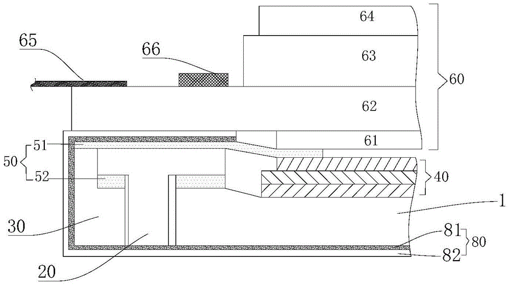
[0024] The backlight module provided in this example, such as figure 2 As shown, it includes: a light guide plate 10 , a light source assembly 20 , and a plastic frame 30 installed from inside to outside;
[0025] Specifically, the optical film 40 is disposed on the upper surface of the light guide plate 10 , and is sequentially connected to the light source assembly 20 and the plastic frame 30 through the adhesive layer 51 . Wherein, the light source assembly 20 is fixed between the plastic frame 30 and the light guide plate 10 through the adhesive layer 52 . Those skilled in the art are well aware that the adhesive layer 50 used to fix the light source assembly 20 a...
PUM
 Abstract
Description
Claims
Application Information