Pseudo-static test device

A test device and quasi-static technology, applied in the field of quasi-static test devices, can solve the problems of inability to unload quickly, limited loading capacity, difficult to control loading and unloading, etc. Effect

Inactive Publication Date: 2015-09-16
PLA UNIV OF SCI & TECH
View PDF7 Cites 30 Cited by
  • Summary
  • Abstract
  • Description
  • Claims
  • Application Information

AI Technical Summary

Problems solved by technology

The heavy object stacking method has insufficient flexibility and limited loading capacity. When the component is about to fail, it cannot be quickly unloaded, and the full resistance-displacement curve of the component cannot be collected.
Actuator distribution beam distribution loading method is generally two-point or three-point distribution loading, which has a large error compared with uniform loading; moreover, when measuring the full resistance-displacement curve of the component, the component will have a large deformation and a large stiffness The distribution beam cannot guarantee close contact with the component as the component deforms, and it is difficult to control the later loading and unloading, which will also cause large errors
[0004] Therefore, the problem existing in the prior art is: for axially stressed members such as structural columns or constrained beams, the current quasi-static test device cannot realize the joint action of lateral uniform load and axial force. Resistance-displacement full curve test

Method used


Image

  • Pseudo-static test device
  • Pseudo-static test device

Examples


Embodiment Construction

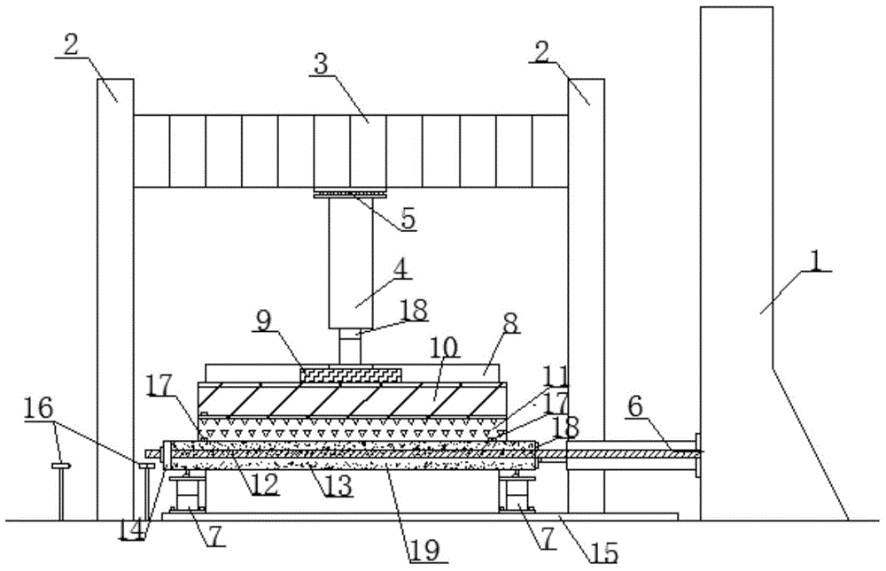
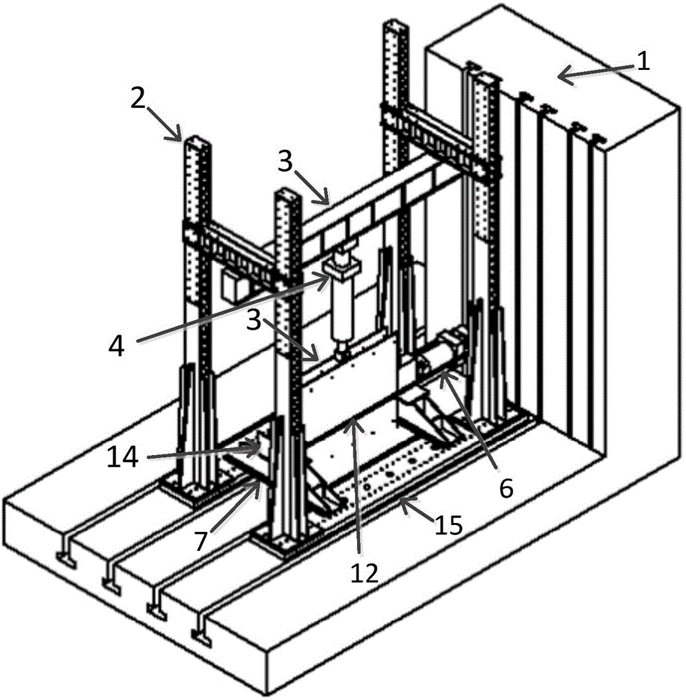
[0018] Such as figure 1 As shown, the quasi-static test device of the present invention is used to test the resistance-displacement full curve of the columnar member 13, including the reaction wall 1 and the door type reaction frame 2, the main beam 3 of the door type reaction frame 2 and the The reaction force wall 1 is vertical to the wall, and also includes a vertical actuator 4. The upper end of the vertical actuator 4 is connected to the main beam 3 through a ball joint 5, and the lower end of the vertical actuator 4 is pressed against the main beam 3. On the parallel distribution beam 9, it also includes the I-beam 10 placed under the distribution beam 9 and the water bag 11 placed under the I-beam 10, the column member 13 to be measured is placed under the water bag 11, and the The ground transition plate 15 and the two curved supports 7 fixed on the ground transition plate 15, the two curved supports 7 are located at the lower part of the column member 13 to be measure...


PUM


Abstract

The invention discloses a pseudo-static test device which comprises a reaction wall (1) and a gate-type reaction frame (2). A main beam (3) of the gate-type reaction frame (2) is vertical to the wall surface of the reaction wall (1); the upper end of a vertical actuator (4) is connected with the main beam (3) through a spherical hinge (5), and the lower end is pressed on a distribution beam (9) parallel with the main beam (3). The pseudo-static test device also comprises an H-shaped steel beam (10), a water sac (11) and a columnar member to be tested (13) which are arranged under the distribution beam (9) in sequence. Two bending supports (7) are arranged under the columnar member to be tested (13) close to the two ends respectively. The pseudo-static test device also comprises an anchor rod (12), a steel baffle plate (14) and a horizontal actuator (6). One end of the anchor rod (12) passes through the steel baffle plate (14), and the other end is connected to a vertical channel in the reaction wall (1) through a bolt. The pseudo-static test device can test resistance-displacement full curves of beams and columns and the like under the combined actions of transverse uniform distribution load and axial force two loads.

Description

technical field [0001] The invention belongs to the technical field of mechanical testing of building structures, in particular to a quasi-static testing device capable of testing the resistance-displacement full curve of components such as beams and columns under the joint action of two types of loads: transverse uniform load and axial force. Background technique [0002] As the main force-bearing components of building structures, the response of beams and columns under the action of explosion is an important content of the anti-blast research of building structures. Due to the danger, destructiveness, high cost, and difficulty of testing in the explosion test, in the actual research, the explosion load is equivalent to a uniformly distributed load for pseudo-static loading through an equivalent method, and the component’s force is measured by the pseudo-static test. The full resistance-displacement curve can be used to study the anti-knock performance of components. [0...

Claims


Application Information

Patent Timeline
Patent Type & Authority Applications(China)
IPC IPC(8): G01M13/00
Inventor 陈力方秦潘腾张亚栋相恒波柳锦春
Owner PLA UNIV OF SCI & TECH
Why Eureka
Try Eureka