Transformer radiator with fixedly connected telescopic external fins and detachably connected internal fins
A technology for dismantling connections and inner fins, applied in transformer/inductor cooling, laminated components, heat exchange equipment, etc., can solve the problems of poor heat dissipation of transformer radiators, achieve good shock isolation effect, good heat dissipation effect, The effect of improving the cooling effect
- Summary
- Abstract
- Description
- Claims
- Application Information
AI Technical Summary
Problems solved by technology
Method used
Image
Examples
Embodiment 1
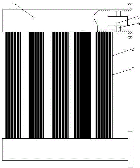
[0035] Embodiment one, see figure 1 , a transformer radiator with telescopic outer fins fixedly connected and inner fins detachably connected, comprising two oil pipes 1 and a plurality of cooling fins 2 connected between the two oil pipes. The two oil pipes 1 are distributed up and down and extend horizontally. A circulation pump 5 is arranged in the upper oil pipe of the oil pipe 1 . The circulation pump 5 is suspended in the oil pipe 1 through four vibration isolation blocks 9 . A plurality of outer fins 7 are arranged outside the heat sink 2 .
[0036] see figure 2 , The heat sink 2 is provided with a flow channel 21 . Runner 21 connects two oil pipes 1 (see figure 1 ) connectivity. The flow channel 21 is provided with a plurality of inner card slots 23 . The inner slot 23 is a linear slot extending in the vertical direction. Several inner fins 3 are arranged in the flow channel 21 . The inner fin 3 is provided with an inner fin portion clamping head 31 . The in...
Embodiment 2
[0048] Embodiment two, the difference with embodiment one is:
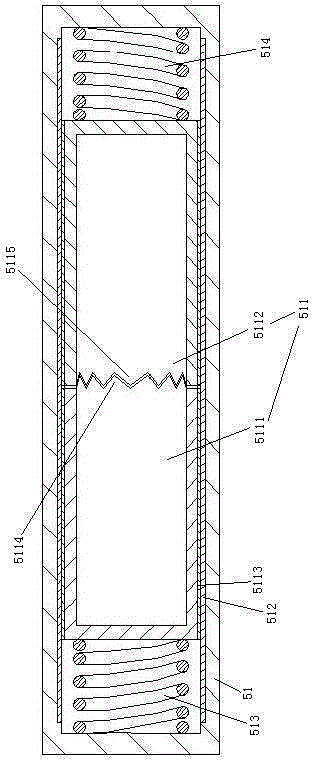
[0049] see Figure 10 , the pump shaft 51 is pierced with a circular inner rod 511 . The inner rod 511 is a tubular structure. The inner surface of the pump shaft 51 is provided with an inner friction layer 512 . The inner rod 511 includes a left rod 5111 and a right rod 5112 . The outer peripheral surfaces of the left rod 5111 and the right rod 5112 are provided with an outer friction layer 5113 . The outer friction layer 5113 covers the inner rod 511 along the circumference of the inner rod 511 . The left end of the left rod 5111 is connected with the pump shaft 51 through the left energy-absorbing spring 513 . The right end surface of the left rod 5111 is provided with a plurality of first reversing teeth 5114 distributed along the circumferential direction of the left rod. The right end of the right rod 5112 is connected with the pump shaft 51 through the right energy-absorbing spring 514 . The left end...
Embodiment 3
[0051] Embodiment three, the difference with embodiment two is:
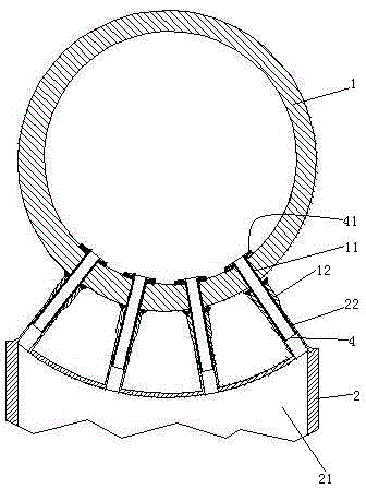
[0052] see Figure 11, The heat sink 2 is provided with a number of connecting pipes 22 communicating with the flow channel 21 . The oil pipe 1 is provided with several oil holes 11 . The outer end of the oil hole 11 is connected with a pipe seat 12 . The pipe base 12 and the oil pipe 1 are welded together. The inner pipe 4 is pierced in the oil hole 11 . The inner end of the inner tube 4 is provided with a flange 41 . The inner tubes 4 pass through the tube bases 12 and penetrate into the connecting tubes 22 one by one to realize the communication between the oil tube 1 and the flow channel 21 in the cooling fin 2 .
[0053] see Figure 12 , The flange 41 is hooked on the inner peripheral surface of the oil pipe 1 . The flange 41 and the inner peripheral surface of the oil pipe 1 are only connected together by abutting. The junctions of the pipe base 12 , the inner pipe 4 and the connecting pipe 22 are ...
PUM
 Abstract
Description
Claims
Application Information
 - R&D
- Intellectual Property
- Life Sciences
- Materials
- Tech Scout
- Unparalleled Data Quality
- Higher Quality Content
- 60% Fewer Hallucinations
Browse by: Latest US Patents, China's latest patents, Technical Efficacy Thesaurus, Application Domain, Technology Topic, Popular Technical Reports.
© 2025 PatSnap. All rights reserved.Legal|Privacy policy|Modern Slavery Act Transparency Statement|Sitemap|About US| Contact US: help@patsnap.com


