Coupler

A technology of couplers and coupled conductors, applied in the field of couplers, can solve the problems of the change of the strength of the two-way coupled signal and the difficulty of designing a two-way coupler, and achieve the effect of increasing the working frequency range

Inactive Publication Date: 2015-09-16
CHENGDU E CHUAN ELECTRONICS TECH
View PDF5 Cites 0 Cited by
  • Summary
  • Abstract
  • Description
  • Claims
  • Application Information

AI Technical Summary

Problems solved by technology

[0003] In the prior art, couplers are required to have a bidirectional coupling function in some occasions. Although some current couplers can have a bidirectional coupling function, with the increase of signal power, bidirectional coupling in certain frequency ranges of UHF The design of the device will become very difficult, and the strength of its two coupling signals will also change, and the adjustment of the structure spacing is required to meet the requirements.

Method used


Image

  • Coupler
  • Coupler

Examples


Embodiment Construction

[0010] The following will clearly and completely describe the technical solutions in the embodiments of the present invention with reference to the accompanying drawings in the embodiments of the present invention. Obviously, the described embodiments are only some, not all, embodiments of the present invention. Based on the embodiments of the present invention, all other embodiments obtained by persons of ordinary skill in the art without making creative efforts belong to the protection scope of the present invention.

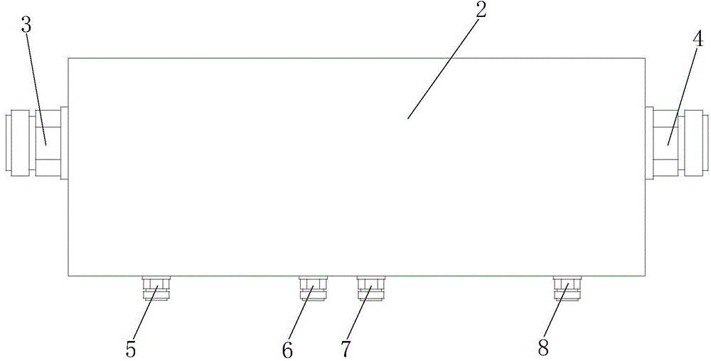
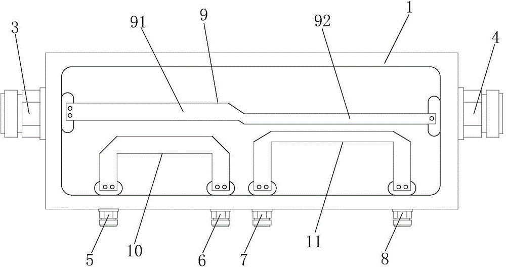
[0011] see figure 1 with figure 2 . The coupler of this embodiment includes a cavity body 1, a cavity cover 2, an input port 3, an output port 4, a first coupled port 5, a first load port 6, a second coupled port 7, a second load port 8, and a transmission conductor 9 , the first coupling conductor 10 and the second coupling conductor 11 .

[0012] The chamber cover 2 covers the chamber body 1 and forms an accommodating space with the chamber body 1 , and ...


PUM


Abstract

The invention provides a coupler. The coupler comprises a cavity body, a cavity cover, an input port, an output port, a first coupling port, a first load port, a second coupling port, a second load port, a transmission conductor, a first coupling conductor and a second coupling conductor, wherein an accommodating space is formed by the cavity cover and the cavity body; the transmission conductor, the first coupling conductor and the second coupling connector are arranged in the accommodating space; the input port and the output port are formed in two opposite ends of the cavity body respectively; two ends of the transmission conductor are connected with the input port and the output port respectively; the first coupling port, the first load port, the second coupling port and the second load port are formed in the side face of the cavity body; two ends of the first coupling conductor are connected with the first coupling port and the first load port respectively; two ends of the second coupling conductor are connected with the second coupling port and the second load port respectively; the transmission conductor comprises a first transmission body parallel to the first coupling conductor and a second transmission body parallel to the second coupling conductor. The coupler can realize bidirectional coupling.

Description

technical field [0001] The invention relates to the technical field of communication, in particular to a coupler. Background technique [0002] In modern wireless communication systems, passive devices are widely used for their environmental protection, low power consumption and high reliability. Coupler is a very commonly used device in passive devices. Its main feature is that the coupling loss can be designed according to actual needs. It has the advantages of wide operating frequency, low in-band insertion loss, high isolation, and small standing wave ratio. [0003] In the prior art, couplers are required to have a bidirectional coupling function in some occasions. Although some current couplers can have a bidirectional coupling function, with the increase of signal power, bidirectional coupling in certain frequency ranges of UHF The design of the device will become very difficult, and the strength of its two-way coupling signals will also change, and it is necessary t...

Claims


Application Information

Patent Timeline
Patent Type & Authority Applications(China)
IPC IPC(8): H01P5/12
Inventor 张继宏
Owner CHENGDU E CHUAN ELECTRONICS TECH
Why Eureka
Try Eureka