Directional coupler
一种定向耦合器、耦合端口的技术,应用在波导型器件、电气元件、连接装置等方向,达到抑制耦合度的变化、减少信号反射、简单结构的效果
- Summary
- Abstract
- Description
- Claims
- Application Information
AI Technical Summary
Problems solved by technology
Method used
Image
Examples
no. 1 Embodiment approach
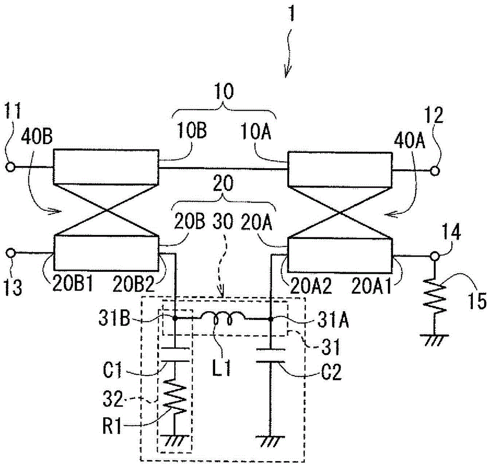
[0049] The following is a detailed description of the embodiments of the present invention with reference to the accompanying drawings. First, refer to figure 1 Furthermore, the circuit configuration of the directional coupler according to the first embodiment of the present invention will be described below. Such as figure 1 As shown, the directional coupler 1 according to this embodiment includes an input port 11 , an output port 12 , a coupling port 13 , and a termination port 14 . The directional coupler 1 further includes a main line 10 connecting the input port 11 and the output port 12 , and a sub line 20 connecting the coupling port 13 and the terminal port 14 . The terminal port 14 is grounded via a terminal resistor 15 . That is, one end of the terminating resistor 15 is connected to the terminating port 14, and the other end of the terminating resistor 15 is connected to the ground. In this embodiment, the resistance value of the terminal resistor 15 is 50Ω.
...
no. 2 Embodiment approach
[0086] Next, refer to Figure 12 Furthermore, the directional coupler 1 according to the second embodiment of the present invention will be described below. Figure 12 It is a circuit diagram showing the circuit configuration of the directional coupler 1 according to this embodiment. In the directional coupler 1 according to this embodiment, the configuration of the low-pass filter 30 is different from that of the first embodiment.
[0087] The low-pass filter 30 according to the present embodiment has the first path 31, the second path 32, and the second capacitor C2 similarly to the first embodiment. The first path 31 has a third end portion 31A connected to the second end portion 20A2 of the first coupling line portion 20A, a fourth end portion 31B on the opposite side, and a third end portion 31A and a fourth end portion provided at the third end portion 31A and the fourth end portion. at least 1 inductor between sections 31B. In the present embodiment, the first path 3...
no. 3 Embodiment approach
[0095] Next, refer to Figure 16 Furthermore, the directional coupler 1 according to the third embodiment of the present invention will be described below. Figure 16 It is a circuit diagram showing the circuit configuration of the directional coupler 1 according to this embodiment. In the directional coupler 1 according to the present embodiment, the sub-line 20 includes the first coupled line section 20A and the low-pass filter 30 , but does not include the second coupled line section 20B. In addition, in the directional coupler 1 according to the present embodiment, the main line 10 includes the first portion 10A, but does not include the second portion 10B. In addition, in the directional coupler 1 according to the present embodiment, the first coupling portion 40A is present, but the second coupling portion 40B is not present.
[0096] The configuration of the low-pass filter 30 according to this embodiment may be the same as that of the first embodiment or the same as ...
PUM
 Abstract
Description
Claims
Application Information
 - R&D
- Intellectual Property
- Life Sciences
- Materials
- Tech Scout
- Unparalleled Data Quality
- Higher Quality Content
- 60% Fewer Hallucinations
Browse by: Latest US Patents, China's latest patents, Technical Efficacy Thesaurus, Application Domain, Technology Topic, Popular Technical Reports.
© 2025 PatSnap. All rights reserved.Legal|Privacy policy|Modern Slavery Act Transparency Statement|Sitemap|About US| Contact US: help@patsnap.com


