
Cutting Fluid Tank

一种切削液、液箱的技术,应用在车削设备、磨削/抛光设备、磨削/抛光安全装置等方向,能够解决切屑堆积在底部、流动停止、流速变慢等问题,达到维持有效容积、维护的负担变小的效果

Inactive Publication Date: 2016-07-06
OKUMA CORP
View PDF9 Cites 6 Cited by
  • Summary
  • Abstract
  • Description
  • Claims
  • Application Information

AI Technical Summary

Problems solved by technology

However, the amount of cutting fluid flowing in the tank body fluctuates depending on the amount of cutting fluid required for machining the workpiece, so the flow rate is not constant, and the flow rate may slow down or stop.
[0010] Furthermore, in addition to securing the maximum capacity for the installation space, there are many cases where equipment such as chip conveyors are arranged, and thus the structure and shape of the tank main body of the cutting fluid tank are subject to various restrictions.
As a result, there is a problem that the inside of the box body is formed with intricate narrow spots, and the cutting fluid containing chips stays in these spots, causing the chips to accumulate at the bottom.
[0020] However, the cutting fluid tank described in Patent Document 1 is limited to the case where the internal structure of the tank main body is simple, and cannot be applied to the case where, for example, a chip conveyor and the like are provided and intricate parts are formed.
[0021] In addition, in the case of the mechanism that forms the eddy flow of the cutting fluid in the tank main body as in the cutting fluid tanks described in Patent Documents 2 and 3, when a chip conveyor or the like is installed in the tank main body, the flow is hindered by it, and the cutting fluid is cut. Fluid flow becomes constant, so chip accumulation may occur
[0022] Furthermore, when a propeller is used as in the cutting fluid tanks described in Patent Documents 4 and 5, the effect is limited to a fixed range within the tank main body, and there is a problem that it is impossible to effectively prevent chips from accumulating in a wide range in the tank main body.

Method used


Image

  • Cutting Fluid Tank
  • Cutting Fluid Tank
  • Cutting Fluid Tank

Examples


Embodiment approach

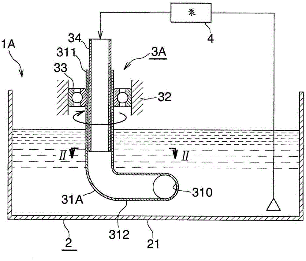
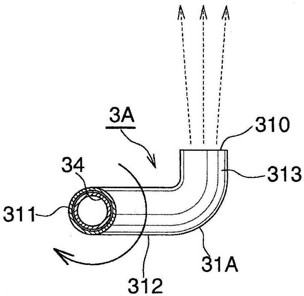
[0070] The cutting fluid tank 1A of the present embodiment has a tank body 2 and a fluid injection device 3A provided in the tank body 2 .

[0071] Although not shown in the figure, the tank main body 2 is disposed below the machining chamber of the machine tool, and the cutting fluid containing chips discharged from the machining chamber passes through a chip conveyor or a filter from a predetermined inflow point (for example, the cutting fluid flow of the chip conveyor) export) inflow.

[0072] In addition, in the box main body 2, there is a cutting fluid supply pump for supplying cutting fluid toward the machining chamber of the machine tool, and at a predetermined position (preferably, a position close to the cutting fluid supply pump), a centrifugal separator or a magnetic separator is provided. A chip separation device composed of a machine, etc.

[0073] In the tank main body 2, the entire cutting fluid including chips forms a liquid flow flowing from the inflow portio...

no. 2 approach

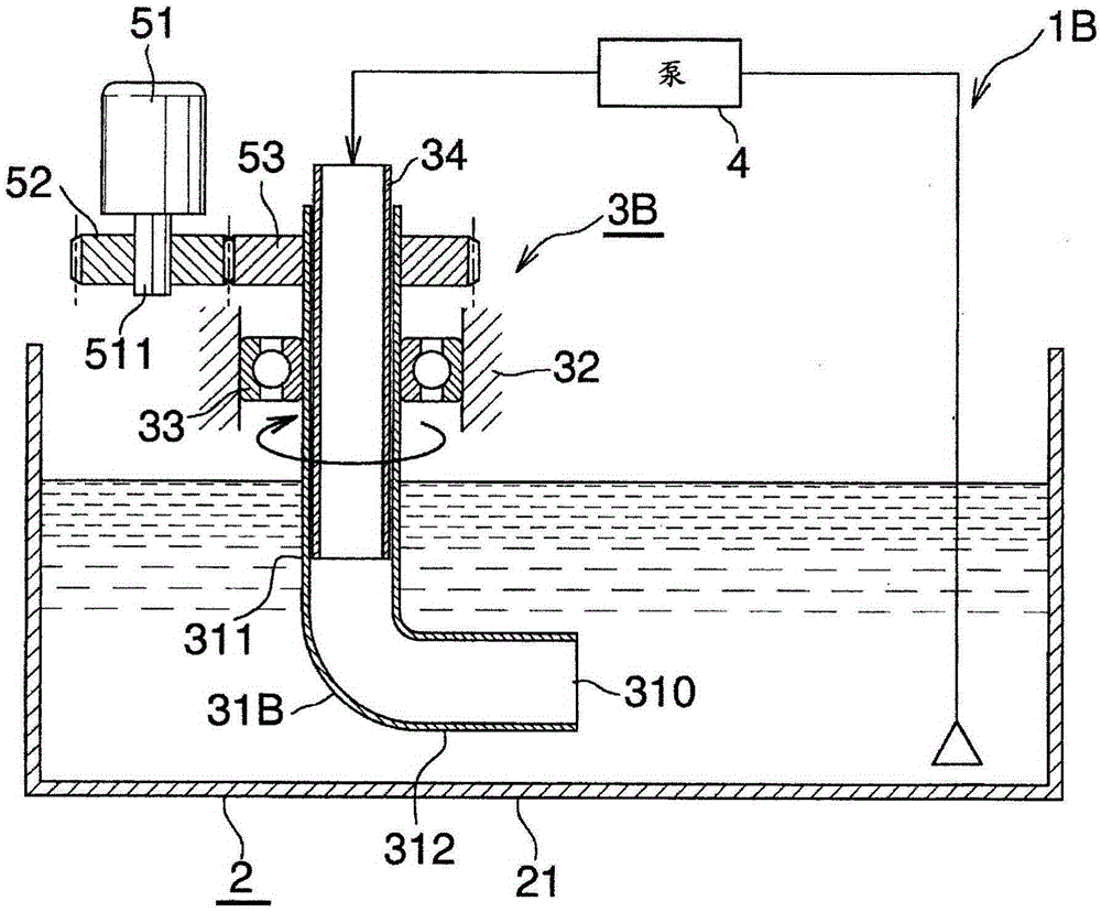
[0082] image 3 The second embodiment of the present invention is shown.

[0083] The cutting fluid tank 1B of the second embodiment is substantially the same as figure 1 and figure 2 The cutting fluid tank 1A of the first embodiment shown is the same.

[0084] That is, in the cutting fluid tank 1B of the present embodiment, the ejection head 31B of the fluid ejection device 3B does not have a curved end, and the ejection port 310 is formed by opening the front end of the lower horizontal cylindrical portion 312 . Therefore, the injection port 310 is oriented in a direction perpendicular to the vertical rotation axis of the injection head 31B.

[0085] Furthermore, the ejection head 31B is rotationally driven by the motor 51 . Specifically, the rotation of the output shaft 511 of the motor 51 is controlled by the drive gear 52 mounted on the output shaft 511 of the motor 51 and the driven gear 53 mounted on the upper end of the spray head 31B in mesh with the drive gear 5...

no. 3 approach

[0087] Figure 4 The third embodiment of the present invention is shown.

[0088] The cutting fluid tank 1C of the third embodiment is substantially the same as figure 1 and figure 2 The cutting fluid tank 1A of the first embodiment shown is the same.

[0089] That is, in the cutting fluid tank 1C of the present embodiment, the ejection head 31A of the fluid ejection device 3C is reciprocally rotated within a predetermined rotational angle. The rotation angle of the spray head 31A is limited to 90° by two stoppers 61 and 62 . The first stopper 61 is set so that, when the spray head 31A is positioned so that its spray port 310 faces Figure 4 The rotational position above ( Figure 4 The position shown by the solid line) is in contact with the side surface of the lower horizontal cylindrical portion 312 . In addition, the second stopper 62 is provided so that, when the ejection head 31A is positioned so that its ejection port 310 faces toward Figure 4 The rotational po...


PUM


Abstract

A cutting fluid tank includes: a fluid ejection apparatus configured to eject fluid toward cutting fluid containing chips and to be capable of varying at least one of a direction and a position of ejection with time in an interior of a tank body configured to store the cutting fluid containing the chips flowed from a work portion of a machine tool. The fluid ejection apparatus includes an ejection head having an ejection port rotatable about an axis of rotation. The ejection port is at a twisted position with respect to the axis of rotation, and the ejection head is rotated by a reaction force of the fluid ejected from the ejection port. Part of the cutting fluid stored in the cutting fluid tank is used as the fluid to be ejected from the ejection port.

Description

technical field [0001] The present invention relates to a cutting fluid tank used in machine tools such as machining centers and lathes. Background technique [0002] In a machine tool that performs cutting, such as a machining center or a lathe, a cutting fluid is generally used for the purpose of lubricating and cooling a tool, and discharging chips. [0003] The cutting fluid sprayed toward the machining chamber of the machine tool by the cutting fluid supply pump is discharged out of the machining chamber together with chips removed from the workpiece. The discharged cutting fluid flows into and temporarily stores in the main body of the cutting fluid tank after the chips mixed in the cutting fluid are separated and removed by a chip conveyor or a filter, and is then supplied again to the machining chamber by the cutting fluid supply pump. [0004] However, the chips mixed with the cutting fluid cannot be separated and removed 100% by the chip conveyor or the filter, an...

Claims


Application Information

Patent Timeline
Patent Type & Authority Applications(China)
IPC IPC(8): B23Q11/10B23Q11/00
CPCB23Q11/0042B23Q11/1069B23Q11/1084B24B55/02Y10T137/85954B24B55/03Y10T137/86372B05B3/06B23B2250/12B23B27/10B23Q11/0057B01F25/21
Inventor 森村章一
Owner OKUMA CORP
Learn More