Iron core of motor, motor and the manufacture method for iron core of motor

A technology for motors and iron cores, applied in the manufacture of stator/rotor bodies, magnetic circuit shapes/styles/structures, magnetic circuit static parts, etc., can solve the problem of magnetic property degradation, reduced magnetic properties, and increased wear and damage of punching dies, etc. problem, achieve the effect of reducing cogging torque and torque ripple, preventing the decline of magnetic properties, and improving the bending precision

Inactive Publication Date: 2007-04-25
NIDEC SHIBAURA ZHEJIANG
View PDF0 Cites 3 Cited by
  • Summary
  • Abstract
  • Description
  • Claims
  • Application Information

AI Technical Summary

Problems solved by technology

For this reason, when the steel plate is punched, the impact strength of the punching die decreases at the protruding parts 116, 116' of the steel plate, the wear and damage of the punching die locally becomes larger, and the life of the die decreases, resulting in depreciation and maintenance costs of the punching die. , Increase in equipment maintenance costs and other cost increases
[0008] When the diameter of the hole portion 114 is increased in order to achieve the above-mentioned uniformity of impact strength, the cross-sectional area of ​​the core bending portion 112 serving as a magnetic path between the tooth portions 111 decreases, the magnetic resistance increases, and the magnetic properties deteriorate. When reducing the reluctance, it is necessary to increase the size of the iron core itself, and there is a problem that the motor becomes larger
[0009] In addition, when the above-mentioned straight core 100 is bent to form an annular core, as shown in FIG. At the bending fulcrum of the core bending portion 112, the deformation pressure is locally concentrated, and the deformation pressure generates a large strain in the steel plate. In addition, the strain deformation region is also enlarged, and the iron loss of the core bending portion 112 serving as a magnetic circuit increases, and the magnetic properties are lowered.
[0010] In addition, the occurrence of processing strain when bending the core bending portion 112 or its deviation reduces the shape accuracy (such as roundness, concentricity, coaxiality, etc.) of the ring core, causing noise and vibration of the motor using it.

Method used


Image

  • Iron core of motor, motor and the manufacture method for iron core of motor
  • Iron core of motor, motor and the manufacture method for iron core of motor
  • Iron core of motor, motor and the manufacture method for iron core of motor

Examples


Embodiment Construction

[0034] (first embodiment)

[0035] Next, a first embodiment of the present invention will be described with reference to FIGS. 1 to 7. FIG.

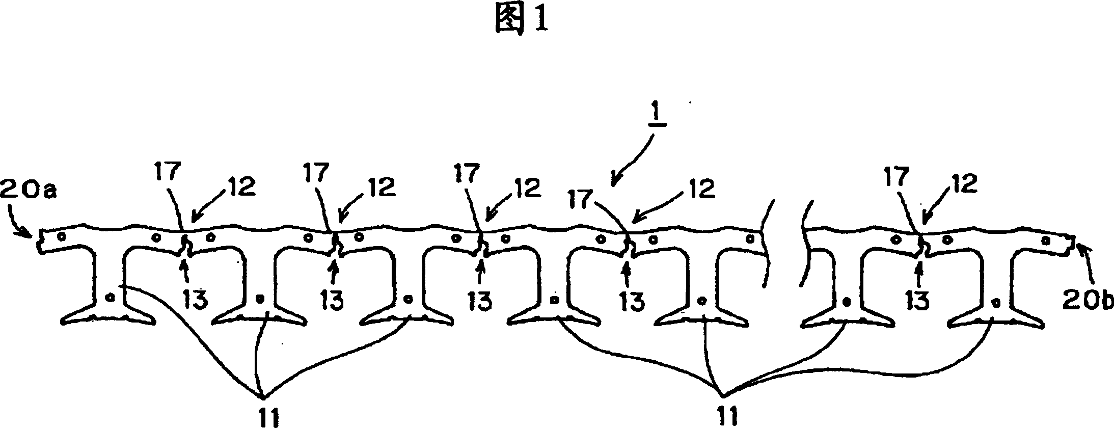
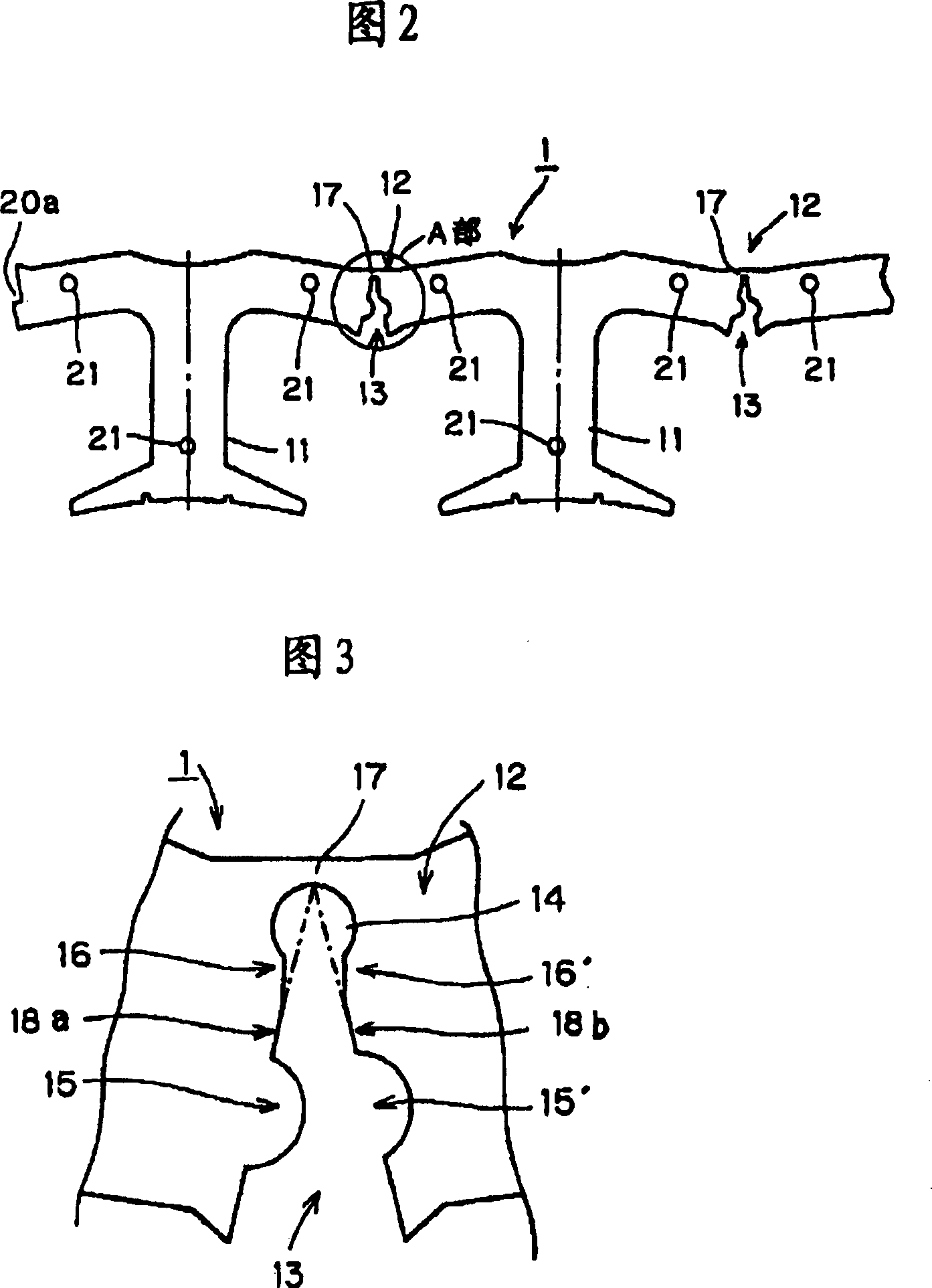
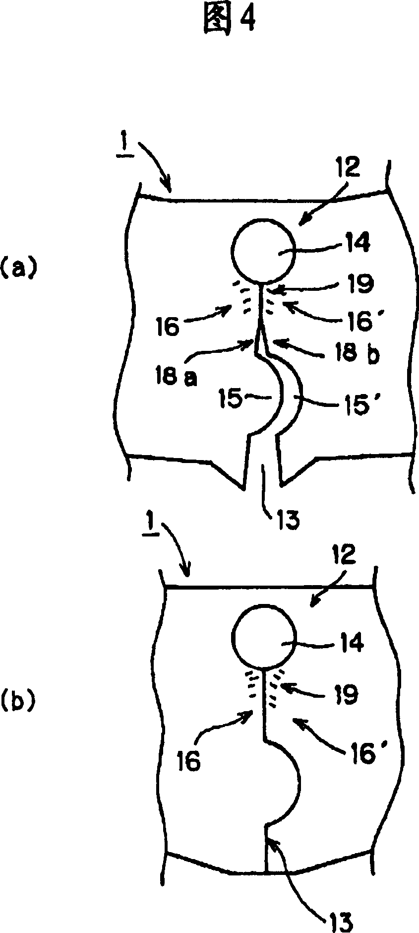
[0036] FIG. 1 is a plan view of a straight iron core 1 constituting an iron core of a brushless DC motor. FIG. 2 is a partial enlarged view of the straight core 1 shown in FIG. 1, and FIG. 3 is an enlarged view of a V-shaped notch (part A in FIG. 2) provided in the bent portion of the core.

[0037] As shown in FIGS. 1 and 2 , the straight core 1 is formed by punching laminated silicon steel sheets with a press using a punching die, and a plurality of T-shaped teeth 11 pass through the core having V-shaped notches 13 The narrow connecting portion 17 at the bottom of the notch portion 13 of the bent portion 12 is connected in a strip shape, and the hole 21 for screwing is opened at a predetermined position, and the connecting portion for bending the straight iron core 1 to be connected into a ring shape is provided at both ends. 20a, 20...


PUM


Abstract

The invention relates to a laminated straight iron core of motor. Wherein, several tooth parts (11) of iron core (1) via the iron core bend part (12) of V-shape cut (13) are connected in band shape; at the direction that closes the V-shape cut (13), the bend part (12) is bended into annular shape; the front part of V-shape cut (13) has hole parts (14); protrusion is arranged opposite to the cut part (13); the part from the hole parts (14) to two sides of front of cut part (13) is parallel cut off, to form stress-proof parts (16, 16'), to improve the service life of punch mould and reduce the stress when bending iron core, to improve the process accuracy.

Description

[0001] This application is a divisional application of the invention patent application filed by Nidec Shibaura Co., Ltd. with the filing date of August 7, 2003 and the application number of "03127561.3". technical field [0002] The present invention relates to a motor core used for a motor such as a brushless DC motor, a motor using the core, and a method for manufacturing the motor core. Background technique [0003] The iron core of a commonly used electric motor is formed in an annular shape by laminating a plurality of straight iron cores, and the straight iron cores are connected with a plurality of teeth punched out of silicon steel plates in a belt shape. [0004] Next, a conventional straight core will be described based on a partial plan view of a strip-shaped straight core 100 shown in FIG. 10 . The straight core 100 is formed by connecting a plurality of tooth portions 111 in a belt shape through a core bending portion 112 having a V-shaped notch portion 113 , a...

Claims


Application Information

Patent Timeline
Patent Type & Authority Applications(China)
IPC IPC(8): H02K1/16H02K15/02
Inventor 村上卓也村上俊明
Owner NIDEC SHIBAURA ZHEJIANG
Why Eureka
Try Eureka