
True density measurement device

A measuring device and a technology of true density, applied to the measuring device, by measuring the pressure difference to determine the specific gravity, the specific gravity measurement and other directions, can solve the problem of not using the structure of the expansion chamber volume can be changed, and achieve the effect of improving the measuring accuracy

Active Publication Date: 2016-10-12
麦奇克拜尔有限公司
View PDF5 Cites 2 Cited by
  • Summary
  • Abstract
  • Description
  • Claims
  • Application Information

AI Technical Summary

Problems solved by technology

In addition, in the device of Patent Document 1, a structure in which the volume of the expansion chamber can be changed is not adopted.

Method used


Image

  • True density measurement device
  • True density measurement device
  • True density measurement device

Examples


Embodiment Construction

[0028] The inventors of the present invention made it possible to change the volume of the expansion chamber to further improve the measurement accuracy. Since it is easier to enter the expansion chamber, the operator can change the volume of the expansion chamber through the simple operation of moving the volume changing member in and out, which can greatly improve the measurement accuracy without causing the disadvantages of increasing the size and cost of the device. .

[0029] In the true density measuring device as an example of the embodiment, the expansion chamber and the sample chamber open in the same direction.

[0030] In a true density measuring device as an example of an embodiment, the true density measuring device has a block in which the sample chamber and the expansion chamber are provided respectively, and the opening of the expansion chamber and the opening of the sample chamber Openings are respectively formed on the upper surfaces of the blocks.

[0031]...


PUM


Abstract

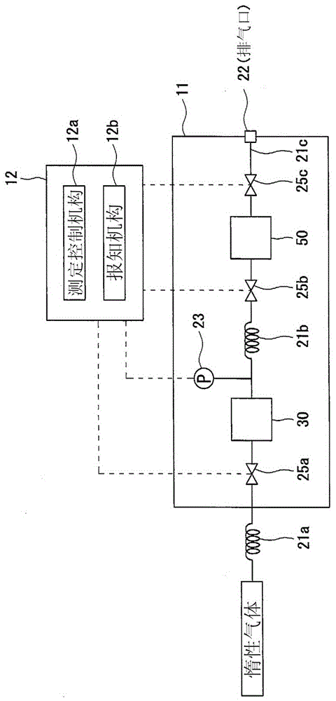
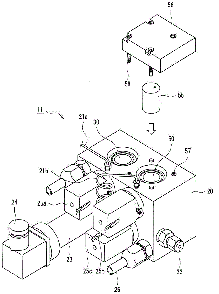
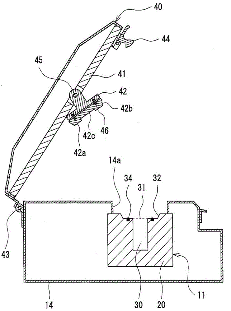
This true density measurement device (10) is a device that is used to measure the true density of a sample (100) by a gas phase substitution method, and is provided with: a sample chamber (30) for accommodating the sample (100), the sample chamber (30) being pressurized through the introduction of an inert gas; and an expansion chamber (50) into which is released the inert gas filling the sample chamber (30). The expansion chamber (50), under conditions of normal use, is opened and closed by a detachable cover (42), and the volume thereof is modified by insertion or withdrawal of a volume modification member (55).

Description

technical field [0001] The invention relates to a true density measuring device for measuring the true density of a measuring object by a gas phase displacement method. Background technique [0002] The true density measurement based on the gas phase displacement method is to fill the sample chamber of the measurement object with an inert gas such as helium (He), and then release the inert gas into the expansion chamber, and the pressure in the sample chamber changes with this release. , based on which the volume of the measurement object is obtained and converted into true density. A specific measurement method is specified in Japanese Industrial Standard (JIS) Z8807. [0003] As a true density measuring device by the gas phase displacement method, for example, the device disclosed in Patent Document 1 is known. In addition, in the device of Patent Document 1, a structure in which the volume of the expansion chamber can be changed is not adopted. prior art literature ...

Claims


Application Information

Patent Timeline
Patent Type & Authority Applications(China)
IPC IPC(8): G01N9/26G01N9/02
CPCG01N2009/028G01N9/02G01N9/26
Inventor 仲井和之山崎博実中村薰郷本隆之
Owner 麦奇克拜尔有限公司
Learn More