Remote control type universal wire clamp

A technology of remote control and clamping clamps, which is applied in the direction of electrical connection sockets, etc., which can solve problems such as potential safety hazards and difficulties in changing the direction of clamping wires, and achieve the effect of improving the safety index

Active Publication Date: 2015-09-16
STATE GRID CORP OF CHINA +1
View PDF8 Cites 11 Cited by
  • Summary
  • Abstract
  • Description
  • Claims
  • Application Information

AI Technical Summary

Problems solved by technology

[0007] In view of the problems existing in the above-mentioned prior art, the present invention provides a remote-controlled universal wire clamp, which solves the problems in the prior art that it is difficult to change the direction of the clamping wire during the electrical test process and has potential safety hazards

Method used


Image

  • Remote control type universal wire clamp
  • Remote control type universal wire clamp
  • Remote control type universal wire clamp

Examples


Embodiment

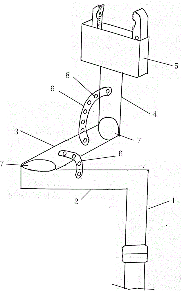
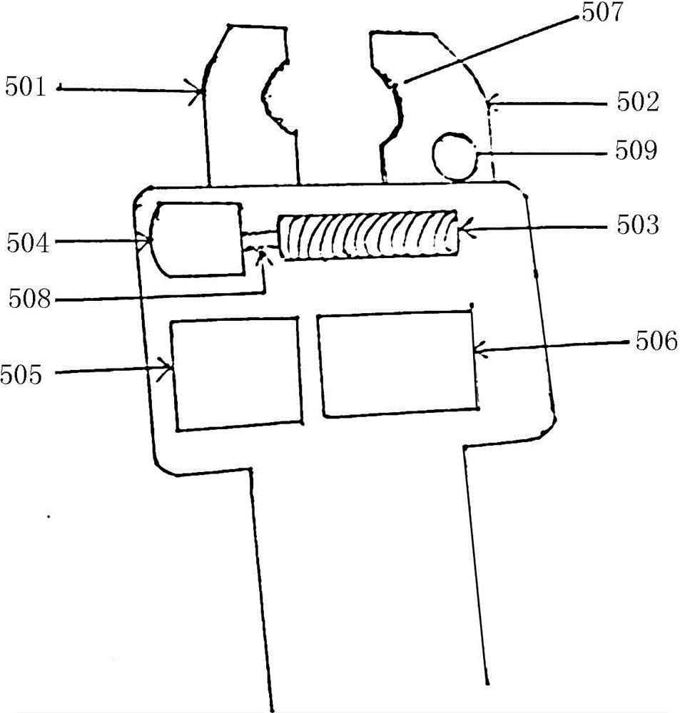
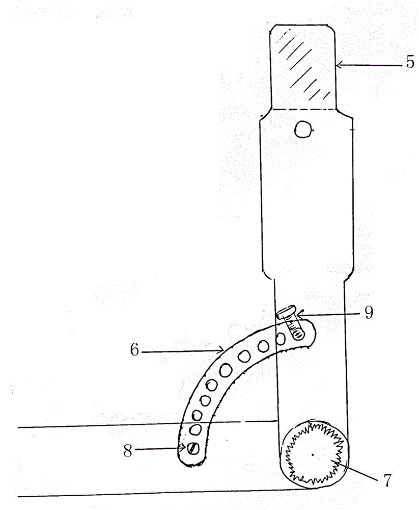
[0029] Such as Figure 1-4 As shown, it includes an operating rod 1, a horizontal rod 2, a connecting rod 3, a support rod 4, a chuck 5 and a limit frame 6. The top end of the operating rod is connected to one end of the horizontal rod, and the other end of the horizontal rod is connected to the connecting rod through the rotating shaft 7. One end of the connecting rod is connected, the other end of the connecting rod is connected to one end of the supporting rod through the rotating shaft, and the other end of the supporting rod is connected to the chuck. A horizontal limit frame is arranged between the horizontal rod and the connecting rod. A vertical limit frame is arranged between them.

[0030] Described limit frame is made up of arc-shaped limit plate, limit hole 8 and adjusting screw 9, limit hole is evenly spaced on the limit plate, and adjusting screw is set on the limit hole movably, and the outer diameter of adjusting screw and The inner diameter of the limit hole ...


PUM


Abstract

The invention relates to a remote control type universal wire clamp comprising an operating rod, a horizontal rod, a connecting rod, a supporting rod, a chuck, and limiting frames. The top end of the operating rod is connected with one end of the horizontal rod. The other end of the horizontal rod is connected with one end of the connecting rod through a rotating shaft. The other end of the connecting rod is connected with one end of the supporting rod through a rotating shaft. The horizontal limiting frame is arranged between the horizontal rod and the connecting rod. The vertical limiting frame is arranged between the connecting rod and the supporting rod. The remote control type universal wire clamp of the invention has higher safety index, and can adapt to any cunning angle of a lead conductor.

Description

technical field [0001] The invention relates to a remote-controlled universal clamp, which is used in the field of electrical testing and is suitable for testing wiring of lead wire conductors during electrical testing of equipment in substations. Background technique [0002] In modern power production, electrical tests are often performed on the primary equipment of substations, such as handover tests, diagnostic tests and routine tests. During the test process, it is necessary to connect the tested equipment with the test equipment. Traditional wiring equipment has been unable to adapt to the rapid development. Power equipment, on the market, most manufacturers ignore R&D and production due to the poor economics of wiring equipment. However, wiring problems in field tests are closely related to the safety of production in electric companies, and must be highly valued. This patent is based on long-term field operations. Through a large number of Observe, analyze and summar...

Claims


Application Information

Patent Timeline
Patent Type & Authority Applications(China)
IPC IPC(8): H01R11/26
CPCH01R11/26
Inventor 吕树明曹俊林梁山薛小丰刘涛涛张新田野李汉卿候念廷崔航
Owner STATE GRID CORP OF CHINA
Why Eureka
Try Eureka