Motor vehicle bumper system

a technology for bumpers and motor vehicles, applied in the direction of bumpers, vehicle components, buffers, etc., can solve the problems of complicated oil loop design of conventional bumper systems, ineffective shock absorption of fixed motor vehicle bumpers, and ineffective bumper reciprocating cylinders, etc., to reduce the consumption of electricity, effectively absorb shocks, and eliminate the effect of drawbacks

Inactive Publication Date: 2005-08-16
YANG CHIN HUN
View PDF11 Cites 6 Cited by
  • Summary
  • Abstract
  • Description
  • Claims
  • Application Information

AI Technical Summary

Benefits of technology

[0007]The present invention has been accomplished to provide a motor vehicle bumper system, which eliminates the aforesaid drawbacks. It is the main object of the present invention to provide a motor vehicle bumper system, which eliminates the phenomena of dead cylinders (locking of hydraulic cylinders) after receiving a bump. It is another object of the present invention to provide a motor vehicle bumper system, which effectively absorbs shocks upon receiving a bump. It is still another object of the present invention to provide a motor vehicle bumper system, which reduces the consumption of electricity. To achieve these and other objects of the present invention, a motor vehicle bumper system is provided and installed in a motor vehicle, using the flow rate of oil circulating through an oil tank to control pressure and an accumulator with a hydraulic oil pressure sensor to absorb energy upon impact. The motor vehicle bumper system comprises a bumper unit, the bumper unit comprising a bumper, and parallel hydraulic cylinders controlled to move the bumper between an extended position and a retracted position; a control switch means; a pump controlled by the control switch means to pump the oil from the oil tank to the hydraulic cylinders, causing the hydraulic cylinders to move the bumper between the extended position and the retracted position; a pressure-setup pipe unit connected between the hydraulic cylinders, the pump and the oil tank of the motor vehicle, the pressure-set up pipe unit comprising an upper oil chamber connecting pipe connected between the upper oil chambers of the hydraulic cylinders for guiding the oil into the hydraulic cylinders to retract the bumper, a lower oil chamber connecting pipe connected between the lower oil chambers of the hydraulic cylinders for guiding the oil into the hydraulic cylinders to extend out the bumper, a direction control valve adapted to control the connection of the upper oil chamber connecting pipe and the lower oil chamber connecting pipe to the pump and the oil tank of the motor vehicle, a branch pipe extended from the lower oil chamber connecting pipe to the oil tank a decompression valve installed in the branch pipe; and a pressure-relief pipe unit, the pressure-relief pipe unit comprising an accumulator, a pipe connected between the lower oil chamber connecting pipe and the accumulator, and a relief valve installed in the pipe between the lower oil chamber connecting pipe and the accumulator. When the control switch means is switched on, the decompression valve and the relief valve are closed, the direction control valve is in action, and the pump is started to pump the oil to the hydraulic cylinders to extend the bumper outward, and then the decompression valve and the relief valve are opened after the bumper has been extended out. When the control switch means is switched off, the decompression valve and the relief valve are closed; the direction control valve is reversed, enabling the hydraulic cylinders to retract the bumper.
[0008]Further, the pressure relief pipe unit of the motor vehicle bumper system comprises a hydraulic oil pressure sensor coupled to the air bag of the motor vehicle and adapted to control the explosion time of the air bag subject to the change of the hydraulic oil pressure, so as to accurately and quickly explode the air bag, preventing a secondary injury to the driver and improving the safety index upon an impact of the motor vehicle.

Problems solved by technology

These fixed motor vehicle bumpers are less effective in absorbing shocks upon receiving a bump.
In the case where the driver does not step on the brake upon receiving a bump, the bumper reciprocating cylinders do not work.
The oil loop design of conventional bumper systems is complicated, and consumes much electricity during operation.
Because the explosion time is subject to the variation of the air pressure, the reaction speed is slow, and the high temperature produced during explosion may burn the user, and the explosion of the air bag may injure the car driver's neck.

Method used


Image

  • Motor vehicle bumper system
  • Motor vehicle bumper system
  • Motor vehicle bumper system

Examples


Embodiment Construction

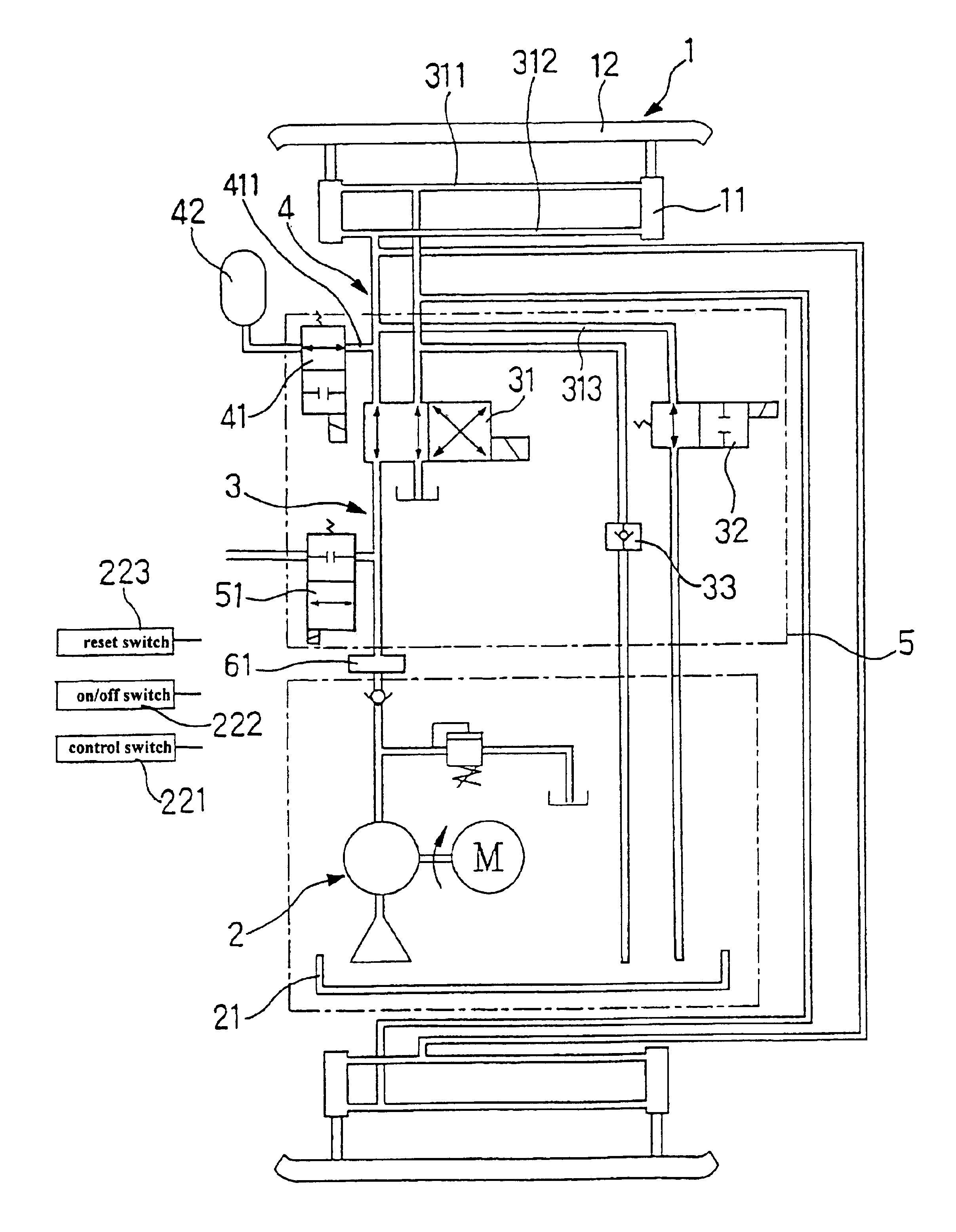
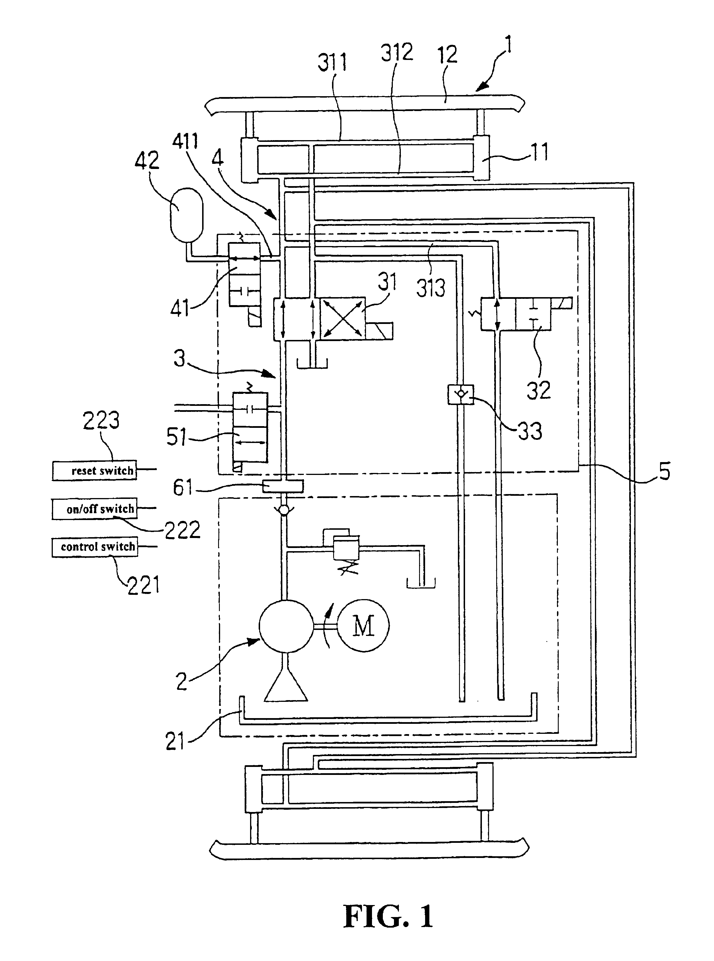
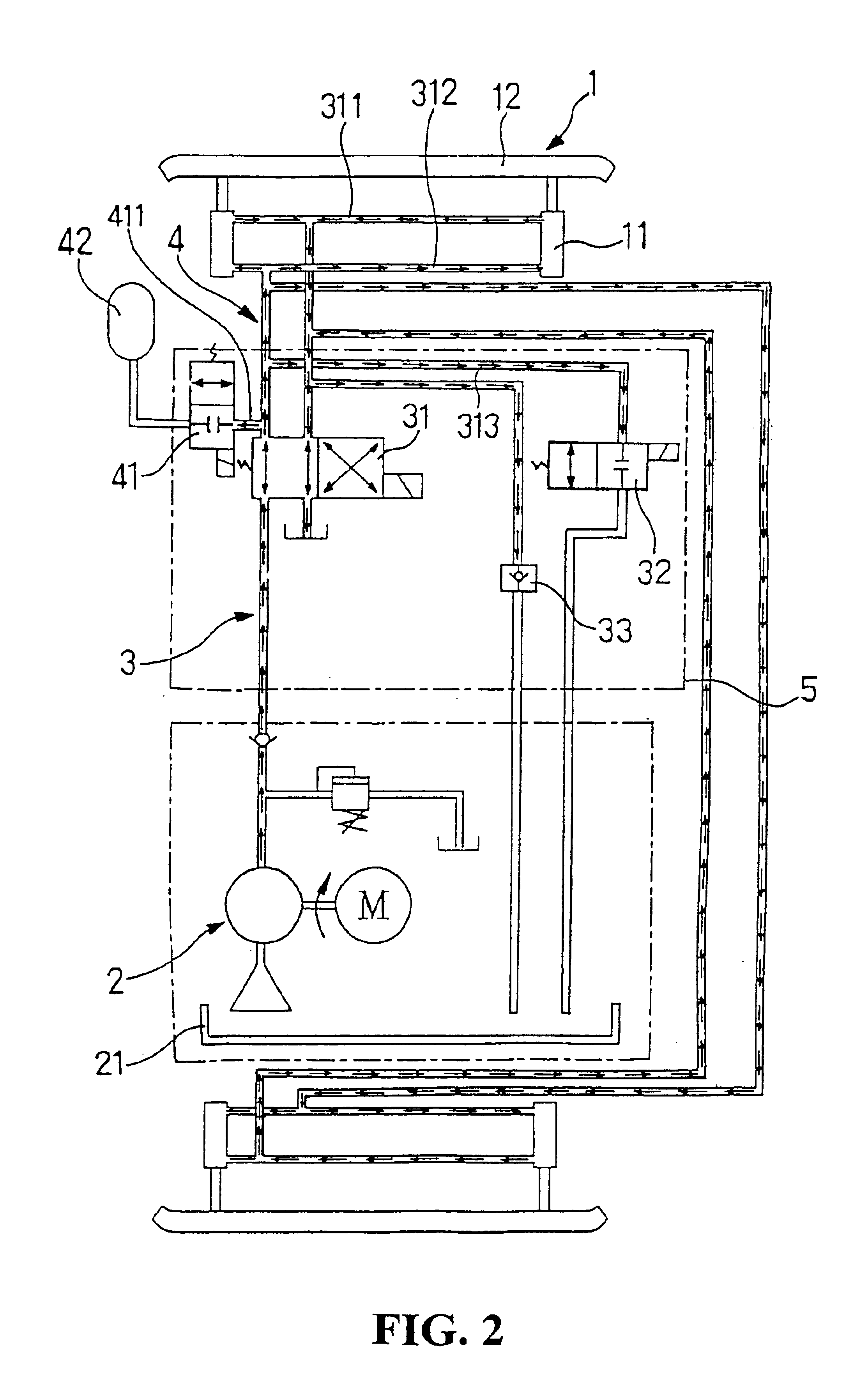
[0017]Referring to FIG. 1, a motor vehicle bumper system in accordance with the present invention is shown comprised of a bumper unit 1, a pump 2, a pressure-setup pipe unit 3, and a pressure-relief pipe unit 4.

[0018]The bumper unit 1 comprises two parallel hydraulic cylinders 11, and a bumper 12 coupled to the hydraulic cylinders 11 at the front side. (Two bumper units may be provided, and respectively installed in the front and rear side of the motor vehicle).

[0019]The pump 2 is connected between the hydraulic cylinders 11 and an oil tank 21, and controlled by an on / off switch 222 to provide a pressure source for extending and retrieving the bumper unit 1. The control switch 221 can be operated synchronously with the ignition switch of the motor vehicle. Further, a reset switch 223 is installed in the motor vehicle, and adapted to start the pump 2 to extend out the bumper unit 1 each time the bumper 12 is bumped.

[0020]Normally, when the hydraulic cylinder of the present invention ...


PUM


Abstract

A motor vehicle bumper system includes a bumper unit having pairs of hydraulic cylinders controlled to move a bumper between an extended position and a retracted position, a pump controlled to pump the oil from an oil tank to the hydraulic cylinders to move the bumper between the extended position and the retracted position, a pressure-setup pipe unit connected between the hydraulic cylinders, the pump and the oil tank and equipped with a decompression valve and controlled by a direction control valve to let the oil be alternatively pumped to the upper oil chambers and lower oil chambers of the hydraulic cylinders to retract or extend out the bumper, and a pressure-relief pipe unit using a relief valve and an accumulator to release pressure from the hydraulic cylinders and a hydraulic oil pressure sensor to control the explosion time of the air bag of the motor vehicle.

Description

CROSS-REFERENCE TO RELATED APPLICATION[0001]This application is a continuation-in-part of the patent application Ser. No. 10 / 122,004, filed Apr. 11, 2002 now abandoned.BACKGROUND OF THE INVENTION[0002](a) Technical Field of the Invention[0003]The present invention relates to a motor vehicle bumper system and, more particularly, to an anti-locking motor vehicle bumper system, which has a multi-direction oil loop that effectively absorbs shocks upon receiving a bump.[0004](b) Description of the Prior Art[0005]A variety of bumper systems and airbag systems have been disclosed for motor vehicles to protect the driver against impact from an outside source. Conventional motor vehicle bumpers are fixed in place. These fixed motor vehicle bumpers are less effective in absorbing shocks upon receiving a bump. There are also known movable motor vehicle bumper designs that enable the front or rear bumper to move upon impact, so as to effectively lessen the shock of sudden impact. According to c...

Claims


Application Information

Patent Timeline
Patent Type & Authority Patents(United States)
IPC IPC(8): B60R19/38B60R19/24B60R19/32
CPCB60R19/38B60R19/32
Inventor YANG, CHIN-HUN
Owner YANG CHIN HUN
Why Eureka
Try Eureka