Suspension assembly of vehicle seat

a vehicle seat and suspension assembly technology, applied in the direction of vehicles, chairs, vehicle components, etc., can solve the problems of occupant discomfort, occupant's entire supporting strength decrease, and it is difficult to completely adapt to the change in the seating position of the occupant, so as to achieve advantageously absorb shock, improve occupant's comfort, and absorb shock

Inactive Publication Date: 2012-05-31
HYUNDAI MOTOR CO LTD +2
View PDF21 Cites 22 Cited by
  • Summary
  • Abstract
  • Description
  • Claims
  • Application Information

AI Technical Summary

Benefits of technology

[0024]First, the invention increases a contact area between the occupant's back and the lumbar plate during vehicle operation and effectively absorbs shocks through the elastic wire section connected to the edge of the lumbar plate, thereby advantageously improving the occupant's comfort.
[0025]Second, the invention provides self-elasticity by realizing the lumbar plate having widthwise irregularities, while supporting the occupant's back with a rigid lumbar plate, thereby advantageously absorbing a portion of shock applied during vehicle operation.
[0026]Third, the invention provides a simple structure between the lumbar plate and the elastic wire section, thereby advantageously reducing the number of manufacturing processes and the manufacturing cost, and the possibility of failure, and facilitating assembly.

Problems solved by technology

However, it is somewhat difficult to completely adapt to changes in an occupant's seating position during long-distance travel only using the seat back frame and the seat back pad, so that the seat back is equipped therein with a shock absorber for surrounding the occupant's back in comfort and a suspension device for comfortably supporting the occupant's lumbar region.
However, since in the conventional suspension device, the cross wires are mounted in the lateral direction relative to the occupant's waist, the occupant then feels discomfort.
Further, since the entire of the suspension device is supported by the cross wires and the boundary wire, the entire supporting strength decreases and the manufacturing cost increases.

Method used


Image

  • Suspension assembly of vehicle seat
  • Suspension assembly of vehicle seat
  • Suspension assembly of vehicle seat

Examples


Embodiment Construction

[0042]Reference will now be made in detail to various embodiments of the present invention(s), examples of which are illustrated in the accompanying drawings and described below. While the invention(s) will be described in conjunction with exemplary embodiments, it will be understood that present description is not intended to limit the invention(s) to those exemplary embodiments. On the contrary, the invention(s) is / are intended to cover not only the exemplary embodiments, but also various alternatives, modifications, equivalents and other embodiments, which may be included within the spirit and scope of the invention as defined by the appended claims.

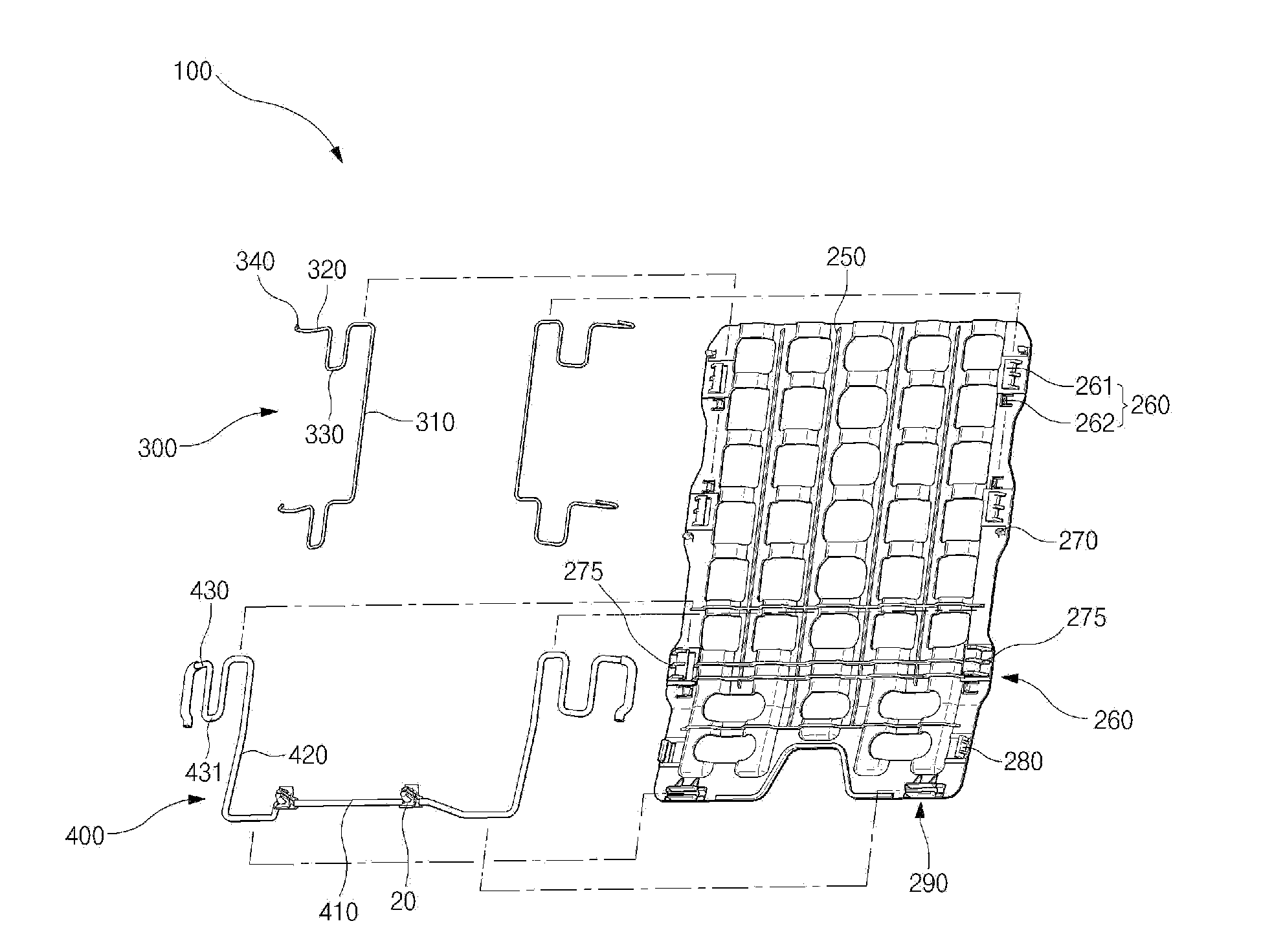
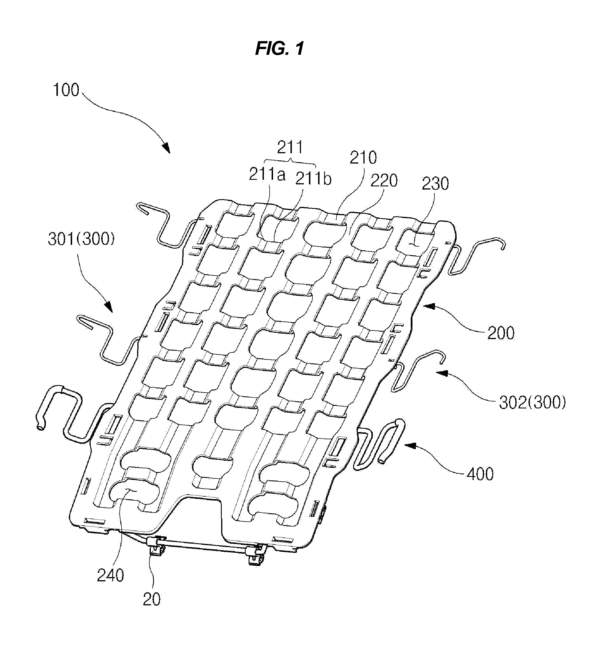
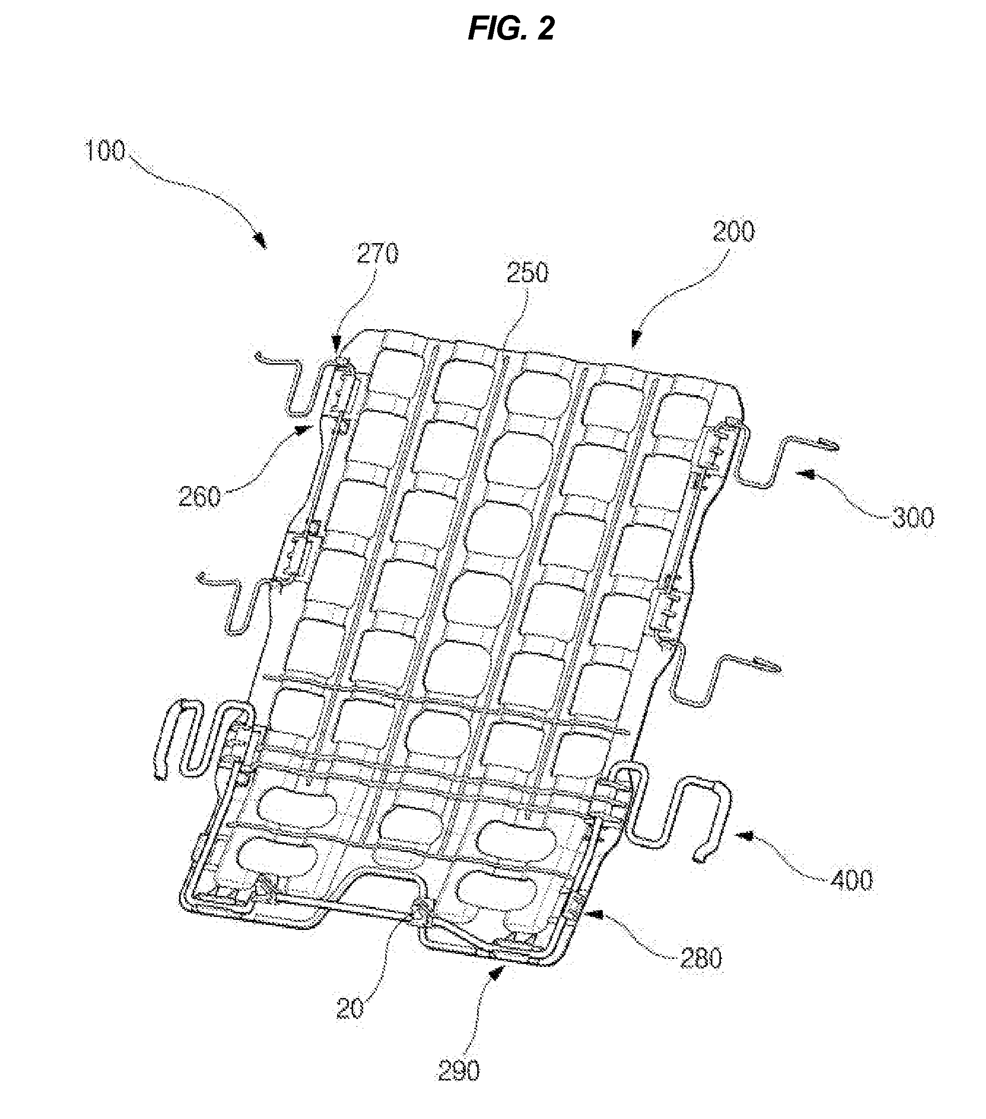
[0043]As shown in FIGS. 1-3, a suspension assembly 100 of a vehicle seat according to an exemplary embodiment of the present invention absorbs shocks occurring during vehicle operation to protect an occupant and provide comfort to the occupant by providing first and second elastic wires 301 and 302, which are elastically connected bet...


PUM


Abstract

A suspension assembly of a vehicle seat may include a lumbar plate disposed within an edge of a seat back frame, and an elastic wire section connecting the edge of the seat back frame with a side of the lumbar plate, wherein the elastic wire section includes a first elastic wire, opposite ends of which may be connected to one edge of the seat back frame and at least a portion thereof may be supported by one side of the lumbar plate, and a second elastic wire, opposite ends of which may be connected to the other edge of the seat back frame and at least a portion thereof may be supported by the other side of the lumbar plate.

Description

CROSS-REFERENCE TO RELATED APPLICATIONS[0001]The present application claims priority to Korean Patent Application No. 10-2010-0119625 filed on Nov. 29, 2010, the entire contents of which is incorporated herein for purposes by this reference.BACKGROUND OF THE INVENTION[0002]1. Field of the Invention[0003]The present invention relates, in general, to a suspension assembly of a vehicle seat and, more particularly, to a suspension assembly of a vehicle seat which effectively absorbs shocks using an elastic wire connected to an edge of a lumbar plate and thus is capable of improving comfort for an occupant.[0004]2. Description of Related Art[0005]Generally, vehicle seats are mounted within a range of restricted space and weight of a vehicle to support occupants in a safe, pleasant manner.[0006]To this end, the seat back includes a seat back frame and a seat back pad to support the waist or back of a driver and passengers. However, it is somewhat difficult to completely adapt to changes i...

Claims


Application Information

Patent Timeline
Patent Type & Authority Applications(United States)
IPC IPC(8): B60N2/66B60N2/68A47C7/46
CPCB60N2/66B60N2/667
Inventor KIM, TAE HYUNGLEE, BONG JOONJEONG, DONG WOOCHO, CHAN KI
Owner HYUNDAI MOTOR CO LTD
Why Eureka
Try Eureka