
Model bottom plate and sand box transfer device

A transfer device and bottom plate technology, applied in casting and forming equipment, metal processing equipment, manufacturing tools, etc., can solve the problems of high requirements on running accuracy, high manufacturing cost and failure rate of transfer roller table, and improve safety production capacity, The effect of improving work reliability and reducing equipment failure rate

Active Publication Date: 2017-03-29
QINHUANGDAO DEV ZONE CHUNGUANG CASTING MACHINERY
View PDF6 Cites 0 Cited by
  • Summary
  • Abstract
  • Description
  • Claims
  • Application Information

AI Technical Summary

Problems solved by technology

The transfer roller table provides the driving force through the sprocket chain drive mechanism, and relies on two rows of side rollers to carry and transfer the model bottom plate and the sand box. The required number of side rollers is relatively large, and the requirements for the running accuracy of the two rows of side rollers are also relatively high. The manufacturing cost and failure rate of the transfer roller table are higher

Method used


Image

  • Model bottom plate and sand box transfer device
  • Model bottom plate and sand box transfer device
  • Model bottom plate and sand box transfer device

Examples


Embodiment Construction

[0012] The specific embodiment of the present invention will be described with reference to the accompanying drawings.

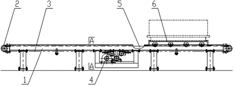
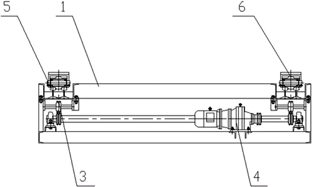
[0013] Such as figure 1 , figure 2 , the base plate of the model and the transfer device of the sand box include a frame 1, and the frame 1 is composed of a steel structure leg and a steel structure upper frame body. Two ends of the frame body on the frame 1 are respectively provided with a pair of sprockets 2, and the pair of sprockets 2 at each end are installed coaxially. A drag chain 3 is assembled on every two front and rear corresponding sprocket wheels 2 . Below the frame body on the frame 1 is positioned at the middle position to be provided with the drag chain drive mechanism 4 that is made up of reduction motor and sprocket chain transmission mechanism, two groups of drive sprocket mechanisms of drag chain drive mechanism 4 are connected with corresponding one respectively Drag the chain 3 to match. Both sides of the upper part of the frame 1 ...


PUM


Abstract

A model bottom plate and sand box transfer device, including a frame, a pair of sprockets are coaxially installed at both ends of the frame, a drag chain is assembled on the two corresponding front and rear sprockets, and a The drag chain drive mechanism is equipped with load-bearing rails composed of two parallel steel rails on both sides of the upper part of the frame. A model bottom plate and sand box hauling device are respectively installed on each load-bearing track. The model bottom plate and sand box haul The device has a channel-shaped load-bearing guide beam, on which there are load-bearing rollers with flanges in the middle of the roller surface, and the roller surfaces on both sides of the flange are respectively matched with the rail surface of the corresponding load-bearing track. Both ends of the guide beam are respectively connected with corresponding drag chains through chain joints. The invention is used in a casting molding line, can ensure the normal transfer of the model bottom plate and the sand box at the T-shaped and cross-shaped intersection positions, can greatly reduce the manufacturing cost of the equipment, and improve the working reliability of the equipment.

Description

technical field [0001] The invention relates to casting production equipment, in particular to a model bottom plate and a sand box transfer device used in cooperation with a motorized roller table. Background technique [0002] At present, the molding and core-making lines in the foundry industry generally use transfer roller tables to transfer the model bottom plates and sand boxes at the T-shaped and cross-shaped intersection positions. The transfer roller table provides the driving force through the sprocket chain drive mechanism, and relies on two rows of side rollers to carry and transfer the model bottom plate and the sand box. The required number of side rollers is relatively large, and the requirements for the running accuracy of the two rows of side rollers are also relatively high. The manufacturing cost and failure rate of the transfer roller table are higher. Contents of the invention [0003] The object of the present invention is to solve the above problems ...

Claims


Application Information

Patent Timeline
Patent Type & Authority Patents(China)
IPC IPC(8): B22C23/00
Inventor 陈锡祥姜永录李国栋
Owner QINHUANGDAO DEV ZONE CHUNGUANG CASTING MACHINERY
Learn More