Discharge lamp lighting circuit

a technology of discharge lamp and lighting circuit, which is applied in the direction of lighting apparatus, light sources, instruments, etc., can solve the problems of inability to escape from such a state, inconvenient miniaturization, and endless reduction of driving frequency of semiconductor switching elements

Inactive Publication Date: 2008-07-08
KOITO MFG CO LTD
View PDF5 Cites 4 Cited by
  • Summary
  • Abstract
  • Description
  • Claims
  • Application Information

AI Technical Summary

Benefits of technology

[0013]The disclosure below describes a measure for preventing a phenomenon that the driving frequency of semiconductor switching elements constituting a DC / AC converter utilizing series resonance is kept to be lower than a resonance frequency, thereby to maintain the lighting state of a discharge lamp or guarantee the shift to a re-lighting operation.
[0018]One or more of the following advantages may be present in some implementations, For example, in order to prevent such a state that, at the time of the reduction of the power source voltage or the grounding etc., the driving frequency of the switching elements reduces and is kept in a capacitive region on the lower frequency side than the resonance frequency, the control is made so as to restore the driving frequency to an inductive region on the higher frequency side than the resonance frequency Fon or Foff.
[0020]As to the detection of the reduction of the driving frequency and the extinction state of the discharge lamp, the discharge lamp lighting circuit further may include a voltage detector which detects a lamp voltage applied to the discharge lamp, and a current detector which detects a lamp current flowing into the discharge lamp, and wherein when a state may be continued for a predetermined time period or more that the lamp voltage detected by the voltage detector is lower than a threshold value and the lamp current detected by the current detector is lower than a threshold value, the driving frequency may be shifted to the frequency region which is higher than the resonance frequency Foff (in this case, the complication etc. of the circuit configuration and the control method etc. can be prevented).
[0022]According to the aforesaid frequency shift control, the reliability and the safety at the time of running etc. can be improved when it is applied to a vehicle lamp, for example.

Problems solved by technology

According to the configuration of performing the two-stage conversion of the DC voltage conversion and the DC / AC conversion, since the size of the circuit becomes large, this configuration is not suitable for miniaturization.
This is because the output voltage tends to reduce with respect to the reduction of the frequency in the frequency region lower than the resonance frequency, whereby the driving frequency of the semiconductor switching element reduces endlessly and it becomes impossible to escape from such a state.
As a result, there may arise such a problem that the discharge lamp can not be lighted again or the controlling of a target power becomes difficult.

Method used


Image

  • Discharge lamp lighting circuit
  • Discharge lamp lighting circuit
  • Discharge lamp lighting circuit

Examples


Embodiment Construction

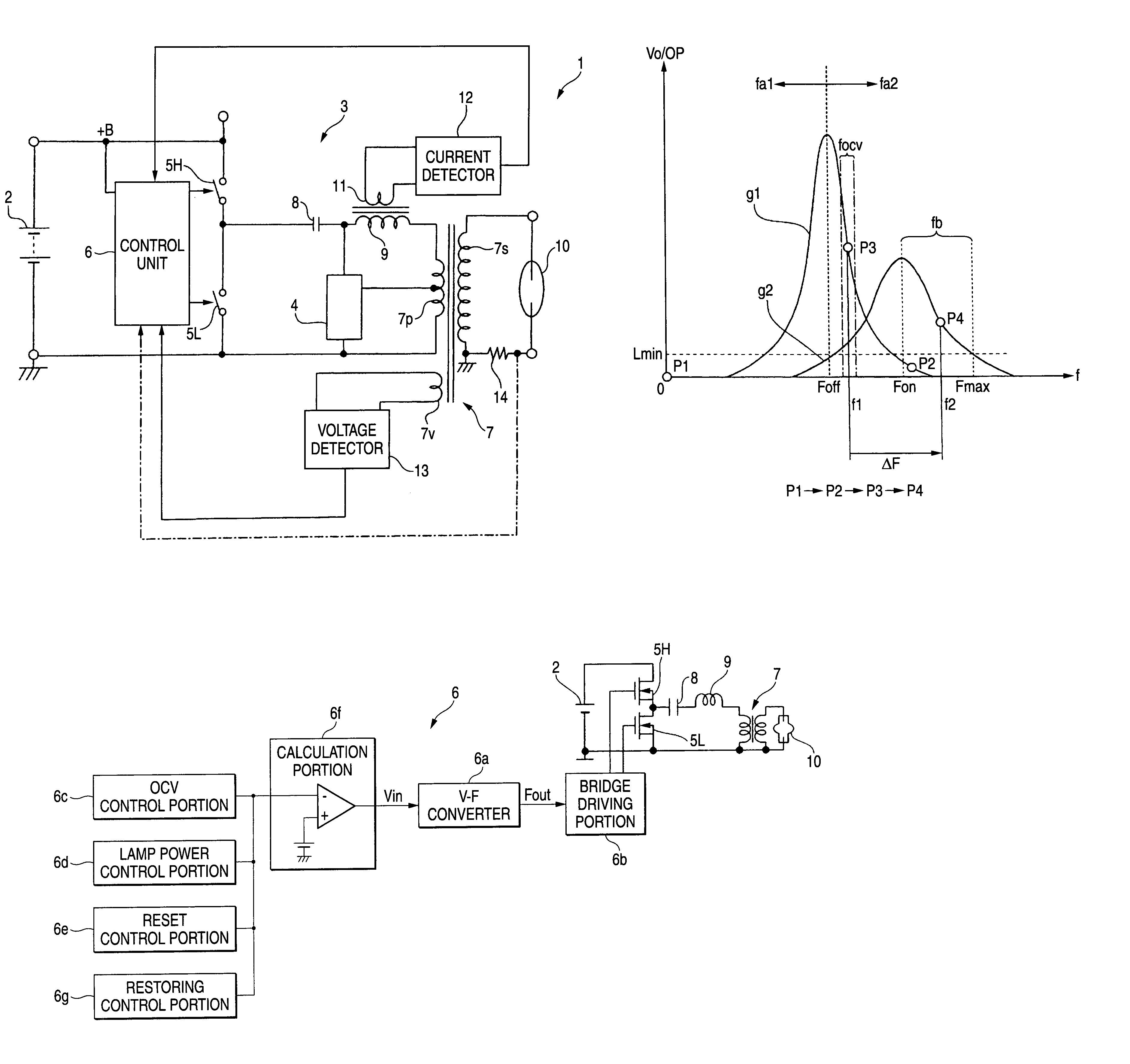
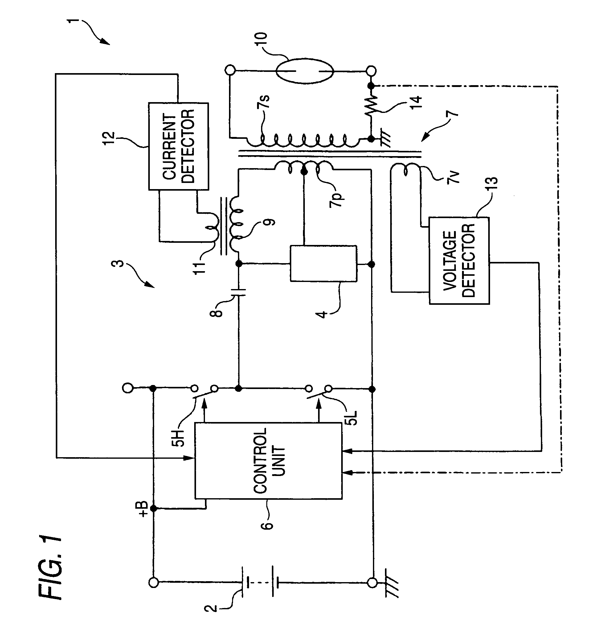
[0037]FIG. 1 is a diagram showing an example of the basic configuration according to the invention, in which a discharge lamp lighting circuit 1 includes a DC / AC converter 3 for receiving power from a DC power source 2 and a starting circuit 4.

[0038]The DC / AC converter 3 is provided so as to receive a DC input voltage (see +B in the figure) from the DC power source 2 and perform the AC conversion and the boosting. In this embodiment, the DC / AC converter includes two switching elements 5H, 5L and a control unit 6 for performing the driving control of these switching elements. That is, the one end of the switching element 5H on the high voltage side is coupled to the terminal of the power source, and the other end of this switching element is grounded via the switching element 5L on the low voltage side. The control unit 6 alternatively turns on and off the two switching elements 5H, 5L. Although each of the switching elements 5H, 5L is represented by a symbol of a switch for the sake...


PUM


Abstract

A discharge lamp lighting circuit includes a DC / AC converter, a starting circuit, a control unit, a plurality of switching elements driven by the control unit and a series LC resonance circuit. At the time of lighting the discharge lamp, the driving frequency of the switching elements is set to a value higher than a resonance frequency at a time of lighting the discharge lamp thereby to drive and control the switching elements. When the driving frequency reduces and the extinction of the discharge lamp is detected, the driving frequency is shifted to a frequency region which is higher than a resonance frequency at a time of extinguishing the discharge lamp thereby to restart the lamp. Further, when the driving frequency reduces to a value lower than the resonance frequency at a time of lighting the discharge lamp during the lighting of the discharge lamp, the driving frequency is restored to a frequency region higher than the resonance frequency at a time of lighting the discharge lamp.

Description

[0001]The present application claims foreign priority based on Japanese Patent Application No. 2005-126620, filed Apr. 25, 2005, the content of which is incorporated herein by reference.BACKGROUND OF THE INVENTION[0002]1. Technical Field[0003]The present invention relates to a discharge lamp lighting circuit to maintain the lighting state thereof and to restart at the time of the extinction or turning-off thereof.[0004]2. Related Art[0005]As a lighting circuit for a discharge lamp such as a metal halide lamp used for an illumination light source for a vehicle, there is the configuration which includes a DC power source circuit having a DC-DC converter, a DC / AC converter and a starting circuit. For example, this configuration is arranged in a manner that a DC input voltage from a battery is converted into a desired voltage by the DC power source, then the desired voltage is converted into an AC output by the DC / AC converter of the succeeding stage, and a start signal is superimposed ...

Claims


Application Information

Patent Timeline
Patent Type & Authority Patents(United States)
IPC IPC(8): H05B37/02
CPCH05B41/2883
Inventor OHTA, SHINJI
Owner KOITO MFG CO LTD
Why Eureka
Try Eureka