
Technique for processing joint where box steel beams with relatively large slenderness ratios of sections are in butt joint

A box-shaped steel girder and processing technology, applied in the processing of building materials, bridges, bridge construction, etc., can solve problems such as unfavorable engineering construction quality control, difficulty in welding lower flange plates, loss of web section, etc., to achieve Convenient construction, convenient welding, high cost effect

Active Publication Date: 2015-09-23
中建五局第三建设有限公司
View PDF5 Cites 3 Cited by
  • Summary
  • Abstract
  • Description
  • Claims
  • Application Information

AI Technical Summary

Problems solved by technology

[0002] The box-shaped steel beam is composed of an upper flange plate, a lower flange plate and two webs on both sides. When two box-shaped steel beams are docked at high altitude, the processing technology for the butt joint of the box-shaped steel beam is adopted in the prior art. The rear welding plate is reserved for the upper flange plate, and the connecting plate needs to be set on the flange opening or the left and right webs and the lower wing web. Deformation
This method is not suitable for the butt connection of box-shaped steel beams with relatively large cross-sections, and the webs generally need to be connected with connecting plates through openings. After welding, they are removed, which increases the cost and causes the loss of the web section, which is not conducive to the construction of the project. The construction quality is controlled, and the section length is relatively large. The box-shaped steel girder cannot be driven into the manhole, and the welding of the lower flange plate is difficult. There will be problems such as hidden quality or defects caused by overhead welding.

Method used


Image

  • Technique for processing joint where box steel beams with relatively large slenderness ratios of sections are in butt joint
  • Technique for processing joint where box steel beams with relatively large slenderness ratios of sections are in butt joint
  • Technique for processing joint where box steel beams with relatively large slenderness ratios of sections are in butt joint

Examples


Embodiment Construction

[0013] The present invention will be further described below in conjunction with accompanying drawing.

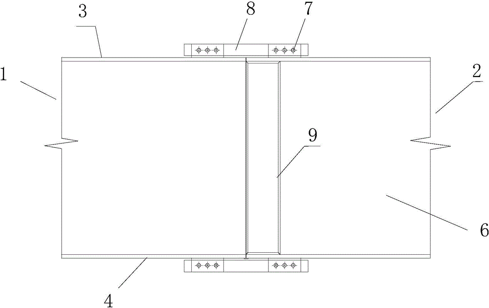
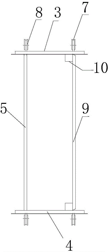
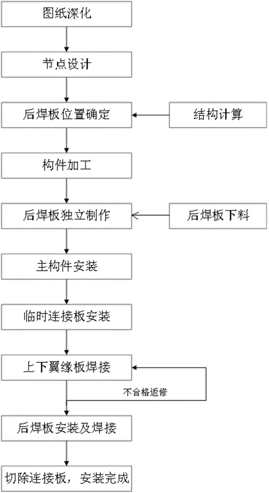
[0014] see figure 1 , figure 2 and image 3 , the treatment process of the butt joint joints of box-shaped steel beams with relatively large slenderness ratio, the first box-shaped steel beam 1 and the second box-shaped steel beam 2 are composed of upper flange plate 3, lower flange plate 4 and the The first web 5 and the second web 6 on both sides are composed, and the rear welding plate 9 is reserved on one of the first web 5 and the second web 6. During installation, the first box steel girder 1 and each of the upper flange plate 3 and the lower flange plate 4 of the second box-shaped steel girder 2 are provided with double connecting lugs 7, and the connecting plates 8 are used to connect the double connecting lugs 7 to connect the first box-shaped steel girder 1 It is butted together with the second box-shaped steel girder 2. After the first box-shaped steel girder...


PUM

PropertyMeasurementUnit
Sizeaaaaaaaaaa

Abstract

The invention discloses a technique for processing a joint where box steel beams with relatively large slenderness ratios of sections are in butt joint. A rear plate is reserved on the side face for butt joint of the box steel beams, an upper flange plate and a lower flange plate are provided with dual connection lug plates and are fixedly connected by means of a connecting plate, flat welding and vertical position welding are used for positioning, so that the upper flange plate, the lower flange plate and two webs of each box steel beam are obtained, and then vertical position welding and horizontal position welding are used for welding a rear weld plate. By the adoption of the technique, the situation that potential quality hazards or defects are caused by over-head position welding occurring during installation of the box steel beams can be reasonably avoided; in addition, installation is convenient, a bolt connecting plate with holes does not need to be additionally arranged on the side face, and thus good economical benefits and good construction period benefits are obtained.

Description

technical field [0001] The invention relates to a processing technology for a butt joint of a box-shaped steel beam, in particular to a processing technology for a butt joint of a box-shaped steel beam with a relatively large section slenderness ratio. Background technique [0002] The box-shaped steel beam is composed of an upper flange plate, a lower flange plate and two webs on both sides. When two box-shaped steel beams are docked at high altitude, the processing technology for the butt joint of the box-shaped steel beam is adopted in the prior art. The rear welding plate is reserved for the upper flange plate, and the connecting plate needs to be set on the flange opening or the left and right webs and the lower wing web. Deformation situation. This method is not suitable for the butt connection of box-shaped steel beams with relatively large cross-sections, and the webs generally need to be connected with connecting plates through openings. After welding, they are rem...

Claims


Application Information

Patent Timeline
IPC IPC(8): E01D21/00E04G21/14
Inventor 刘艳华
Owner 中建五局第三建设有限公司
Learn More