wing anchor

A bolt and wing-type technology, which is applied in the installation of bolts, mining equipment, earthwork drilling and mining, etc., can solve the problems such as the expansion of the end of the bolt, and achieve the effects of good support effect, convenient use and simple structure

Inactive Publication Date: 2017-08-11
XUZHOU UNIV OF TECH
View PDF7 Cites 2 Cited by
  • Summary
  • Abstract
  • Description
  • Claims
  • Application Information

AI Technical Summary

Problems solved by technology

[0003] In order to solve the problem that the existing construction method cannot solve the problem of the expansion of the end of the anchor rod, the present invention provides a wing-type anchor rod, which can achieve the purpose of expanding the end of the anchor section while adapting to the general construction method. Good effect, remarkable engineering benefit

Method used


Image

  • wing anchor

Examples


Embodiment Construction

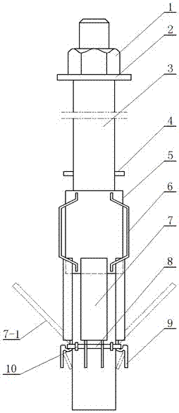
[0011] exist figure 1 Among them, the wing-type anchor rod includes: anchor nut 1, washer plate 2, anchor rod body 3, stop pin 4, push-wing steel pipe 5, positioning rib 6, wing 7, opened wing 7-1, Steel bar ring 8, wing curved ring 9, support station column 10; the wing anchor has a cylindrical anchor body 3, and the bottom of the anchor body 3 is provided with expandable plate-shaped wings 7, Steel bar ring 8 and wing curved ring 9 are provided with support stand column 10 between wing wing bend ring 9 and anchor rod body 3, and support station column 10 is welded together with anchor rod body 3, and wing bend ring 9 ends Welded at the root of the wing 7, and fastened in the hole of the steel ring 8 between the two supporting station columns 10, a push-wing steel pipe 5 is slid on the top of the steel ring 8, and on the surface of the push-wing steel pipe 5 120 degrees evenly distributed and welded with steel positioning ribs 6; on the anchor rod body 3 above the push-wing ...


PUM


Abstract

The wing-type anchor rod is provided with an expandable plate-shaped wing, a steel ring and a wing bend ring at the lower part of the anchor rod body, and a support station column is provided between the wing bend ring and the anchor rod body, and the support station The column and the anchor rod body are welded together, one end of the wing bending ring is welded to the root of the wing, and it is buckled in the hole of the steel ring between the two supporting station columns, and a push wing is slidingly fitted on the top of the steel ring The steel pipe is evenly distributed at 120 degrees on the surface of the thrust wing steel pipe and welded with steel positioning ribs; on the anchor rod body above the push wing steel pipe, there is a backstop pin welded; a washer plate and an anchor screw are installed above the backstop pin cap; the wing-type anchor rod can meet the existing construction conditions and at the same time achieve the purpose of expanding the end of the anchoring section. It has a simple structure, is convenient to use, has a good supporting effect, and has remarkable engineering benefits.

Description

technical field [0001] The invention relates to a bolt used for roadway anchoring, in particular to a wing-type bolt capable of expanding the end of the bolt under the existing construction method. Background technique [0002] In engineering applications, in order to improve the anchoring force of a single anchor, the end of the anchor is often enlarged by the end reaming method, and then the anchor is pulled by grouting. This can increase the stress on the reaming bolt and increase the anchoring effect, but the disadvantage is that the increase in the side resistance of the anchorage section is small, and the force-bearing effect is relatively weak. And because the anchoring force of the anchor rod is mainly provided by the side resistance of the anchorage section, and the stability and reliability of this area directly determine the safety of the entire project, accidents of separation between the rod body and the anchoring body occur from time to time, resulting in serio...

Claims


Application Information

Patent Timeline
Patent Type & Authority Patents(China)
IPC IPC(8): E21D21/00E21D20/02
Inventor 臧秀平唐硕
Owner XUZHOU UNIV OF TECH
Why Eureka
Try Eureka