Blower

A technology of blowing and sucking fans and fans, which is applied in the direction of mechanical equipment, machines/engines, liquid fuel engines, etc. It can solve the problems of affecting the use of users, poor flow expansion effect, and low wind pressure, and achieve the effect of improving the efficiency of fans

Pending Publication Date: 2020-06-26
POSITEC POWER TOOLS (SUZHOU) CO LTD
View PDF0 Cites 0 Cited by
  • Summary
  • Abstract
  • Description
  • Claims
  • Application Information

AI Technical Summary

Problems solved by technology

For the current blower and suction fan, it usually uses a centrifugal fan as the driving device, combined with the traditional straight blowing pipe to carry out the wind. However, although the airflow produced by the centrifugal fan has a relatively high wind speed, its air volume is small and the wind speed is high. The pressure is small, the efficiency of the fan is low, and the straight blowing pipe is used for the air outlet, and the flow expansion effect is poor, and the air volume and wind pressure of the airflow cannot be increased, resulting in the fact that the blowing and suction fan cannot blow wet leaves when it is used, and the fan efficiency is low. Can't achieve the best blowing effect, can't meet the work needs, and affect the user's use

Method used


Image

  • Blower
  • Blower
  • Blower

Examples


Embodiment 1

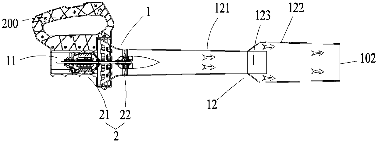
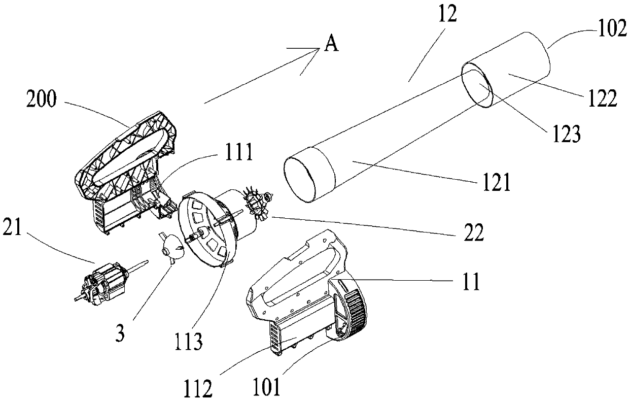
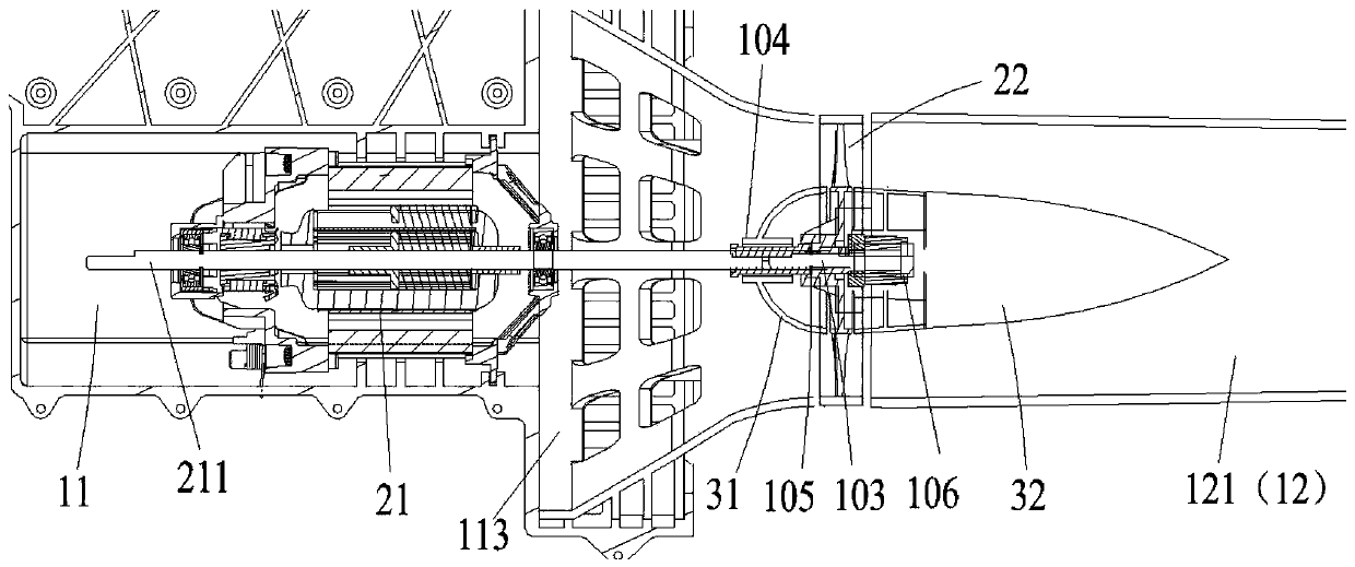
[0055] In this embodiment, the blowing pipe 1-12 includes a main blowing pipe 1-121 and a diffuser pipe 1-122 arranged separately, and a connecting part 1-123 is arranged at the front end of the main blowing pipe 1-121. Specifically, the motor 1-21 used is a high-speed motor with a rotational speed of 32000 RPM. Both the main blowpipe 1-121 and the diffuser pipe 1-122 are obliquely tapered, wherein the main blowpipe 1-121 has a taper of 1.5°, a length of 680mm, and a diameter of 55-65mm. The cross-sectional area in the axial direction is It gradually decreases from the rear end to the front end; the taper of the diffuser pipe 1-122 is 1.8°, the length is 180 mm, and the diameter is 95-105 mm, and its cross-sectional area in the axial direction decreases gradually from the rear end to the front end. The length of the connecting portion 1-123 is 5 mm, that is, the length of the overlapping area between the diffuser pipe 1-122 and the main blow pipe 1-121 is 5 mm. Moreover, the ...

Embodiment 2

[0057] In this embodiment, the blowing pipe 2-12 includes a main blowing pipe 2-121 and a diffuser pipe 2-122 arranged separately, and the connecting part 2-123 is arranged at the front end of the main blowing pipe 2-121. Specifically, the motor 2-21 used is a high-speed motor with a rotational speed of 32000 RPM. Both the main blowpipe 2-121 and the diffuser pipe 2-122 are obliquely tapered, wherein the main blowpipe 2-121 has a taper of 1.5°, a length of 680mm, and a diameter of 55-65mm. The cross-sectional area in the axial direction is It gradually decreases from the rear end to the front end; the taper of the diffuser pipe 2-122 is 1.8°, the length is 180 mm, and the diameter is 95-105 mm, and its cross-sectional area in the axial direction decreases gradually from the rear end to the front end. The length of the connecting portion 2-123 is 20mm, that is, the length of the overlapping area between the diffuser pipe 2-122 and the main blowpipe 2-121 is 20mm. Moreover, the...

Embodiment 3

[0059] In this embodiment, the blowing pipe 3-12 includes a main blowing pipe 3-121 and a diffuser pipe 3-122 arranged separately, and the connecting part 3-123 is arranged at the front end of the main blowing pipe 3-121. Specifically, the motor 3-21 used is a high-speed motor with a rotational speed of 32000 RPM. Both the main blowpipe 3-121 and the diffuser pipe 3-122 are obliquely tapered, wherein the main blowpipe 2-121 has a taper of 1.5°, a length of 680mm, and a diameter of 55-65mm. It gradually decreases from the rear end to the front end; the taper of the diffuser pipe 3-122 is 1.8°, the length is 180mm, and the diameter is 95-105mm, and its cross-sectional area in the axial direction decreases gradually from the rear end to the front end. The telescopic assembly 3-4 is arranged on the connecting portion 3-123 and connected to the diffuser pipe 3-122, and the diffuser pipe 3-122 has no overlapping area with the main blow pipe 3-121. The diffuser pipe 3-122 can shrink...


PUM


Abstract

The invention relates to a blower. The blower comprises a shell and a fan, wherein an air inlet and an air outlet which communicate with the outside are formed in the shell, and the fan is arranged inthe shell and is used for generating an airflow; the fan is an axial flow fan, the axial flow fan comprises a motor and an axial flow fan, and the motor and the axial flow fan are arranged in the same axial direction; and the shell comprises a main part and an air blowing pipe connected with the main part, the air blowing pipe comprises a main blowing pipe and an flow expanding pipe connected with the main blowing pipe, the main blowing pipe is connected with the main part, the main blowing pipe has a connecting part, one side of the flow expanding pipe is connected with the connecting part,the other side of the flow expanding pipe is provided with the air outlet. and a diameter of the flow expanding pipe is larger than that of the connecting part. According to the blower, the axial flowfan is adopted to generate high-speed airflow, the airflow expansion and speed increasing effects are achieved through the air blowing pipe, and the fan efficiency of the blower is greatly improved.

Description

technical field [0001] The invention relates to a blower and suction fan, which belongs to the field of electric tools. Background technique [0002] As a tool for cleaning gardens, streets and other grounds, blower and suction fans are widely used in daily life. At present, the blower is usually composed of a gasoline engine, fan, impeller, and blowing pipe, and the airflow blown out by the blowing pipe cleans the cleaning target. For the current blower and suction fan, it usually uses a centrifugal fan as the driving device, combined with the traditional straight blowing pipe to carry out the wind. However, although the airflow produced by the centrifugal fan has a relatively high wind speed, its air volume is small and the wind speed is high. The pressure is small, the efficiency of the fan is low, and the straight blowing pipe is used for the air outlet, and the flow expansion effect is poor, and the air volume and wind pressure of the airflow cannot be increased, resul...

Claims


Application Information

Patent Timeline
Patent Type & Authority Applications(China)
IPC IPC(8): F04D25/08F04D29/52F04D29/54
CPCF04D25/08F04D29/522F04D29/545
Inventor 刘正伟焦石平刘常华肖海波
Owner POSITEC POWER TOOLS (SUZHOU) CO LTD
Why Eureka
Try Eureka