Fan and fan assembly
a technology of fan and assembly, which is applied in the direction of positive displacement liquid engine, piston pump, liquid fuel engine, etc., to achieve the effect of avoiding turbulence and vortex generation, enhancing fan efficiency, and extending the utility area of the circuit board
- Summary
- Abstract
- Description
- Claims
- Application Information
AI Technical Summary
Benefits of technology
Problems solved by technology
Method used
Image
Examples
first embodiment
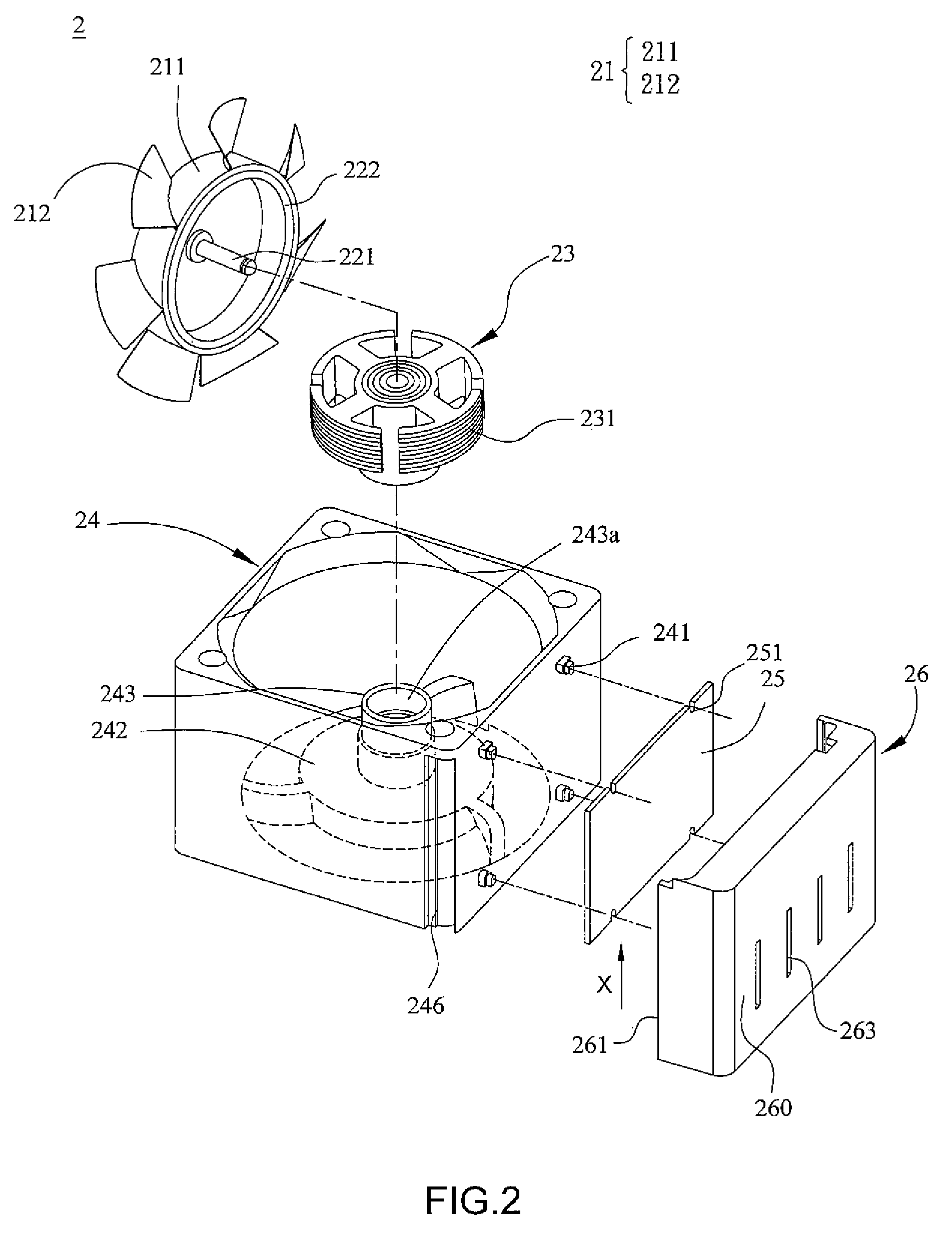
[0018]FIG. 2 is a schematic illustration showing a structure of a fan 2 according to the present invention. Referring to FIG. 2, the fan 2 includes an impeller 21, a motor 23 and a fan frame 24. The impeller 21 includes a hub 211 and a plurality of blades 212 disposed around the hub 211, and there is a rotating shaft 221 connected to the hub 211. The magnetic element 222 is disposed and attached on an inner surface of the hub 211. The magnetic element 222 can be, for example, a permanent magnet, or an electronic magnet. The motor 23 is for driving the impeller 21 to rotate, and the motor 23 includes several silicon steel sheets stacked together and then a coil is wound around these silicon steel sheets. Also, the silicon steel sheets are disposed with respect to the magnetic element 222.
[0019]As mentioned hereinabove, the base 242 has a bearing tube 243 and the base 242 is for supporting the motor 23. When the motor 23 and the impeller 21 are assembled, the rotating shaft 221 is dis...
second embodiment
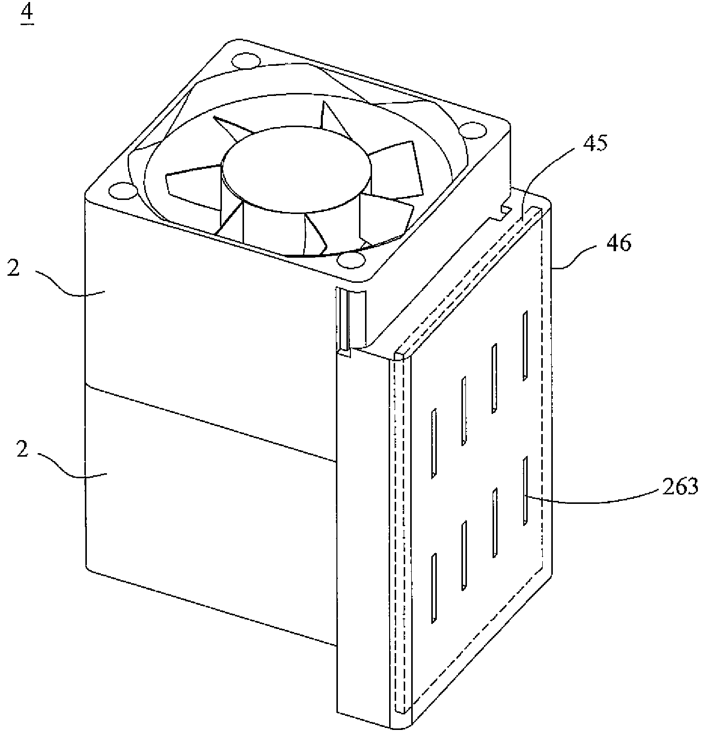
[0027]FIG. 5 is a structure schematic illustration showing another fan assembly 5 according to the preferred embodiment of the present invention. As shown in FIG. 5, the fan assembly 5 includes two fans 3. The number of the fans 3 constituting the fan assembly is not restricted to that shown in FIG. 5, and can be adjusted according to the actual requirements. The structure and the function of each fan 3 are similar to those of the fan of the second embodiment, so detailed descriptions thereof will be omitted. Each fan 3 of the fan assembly 5 has a connecting member 56, which has at least one opening 561. Fan frames 54 of the two fans are connected together so that the common circuit board 55 is disposed in a closed space formed after the two connecting members 56 are combined together to protect the circuit board 55 and the electronic components disposed on the circuit board 55. In addition, the fan assembly 5 of this embodiment has a plurality of heat dissipating holes 341 disposed...
PUM
 Abstract
Description
Claims
Application Information
 - R&D
- Intellectual Property
- Life Sciences
- Materials
- Tech Scout
- Unparalleled Data Quality
- Higher Quality Content
- 60% Fewer Hallucinations
Browse by: Latest US Patents, China's latest patents, Technical Efficacy Thesaurus, Application Domain, Technology Topic, Popular Technical Reports.
© 2025 PatSnap. All rights reserved.Legal|Privacy policy|Modern Slavery Act Transparency Statement|Sitemap|About US| Contact US: help@patsnap.com


