

Centrifugal multiblade fan
- Summary
- Abstract
- Description
- Claims
- Application Information
AI Technical Summary
Benefits of technology
Problems solved by technology
Method used
Image

Examples
first embodiment
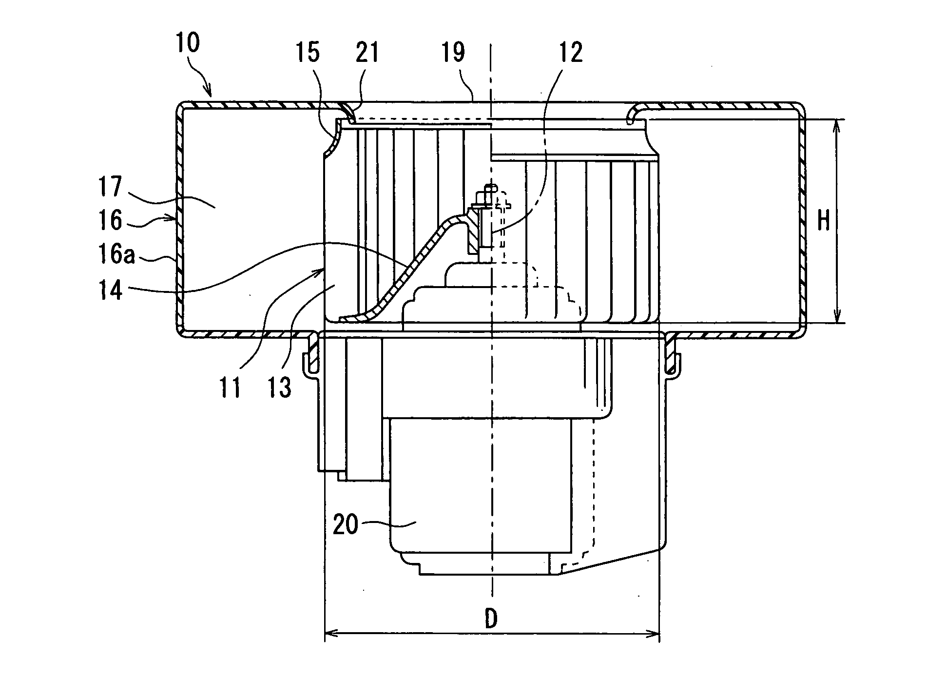
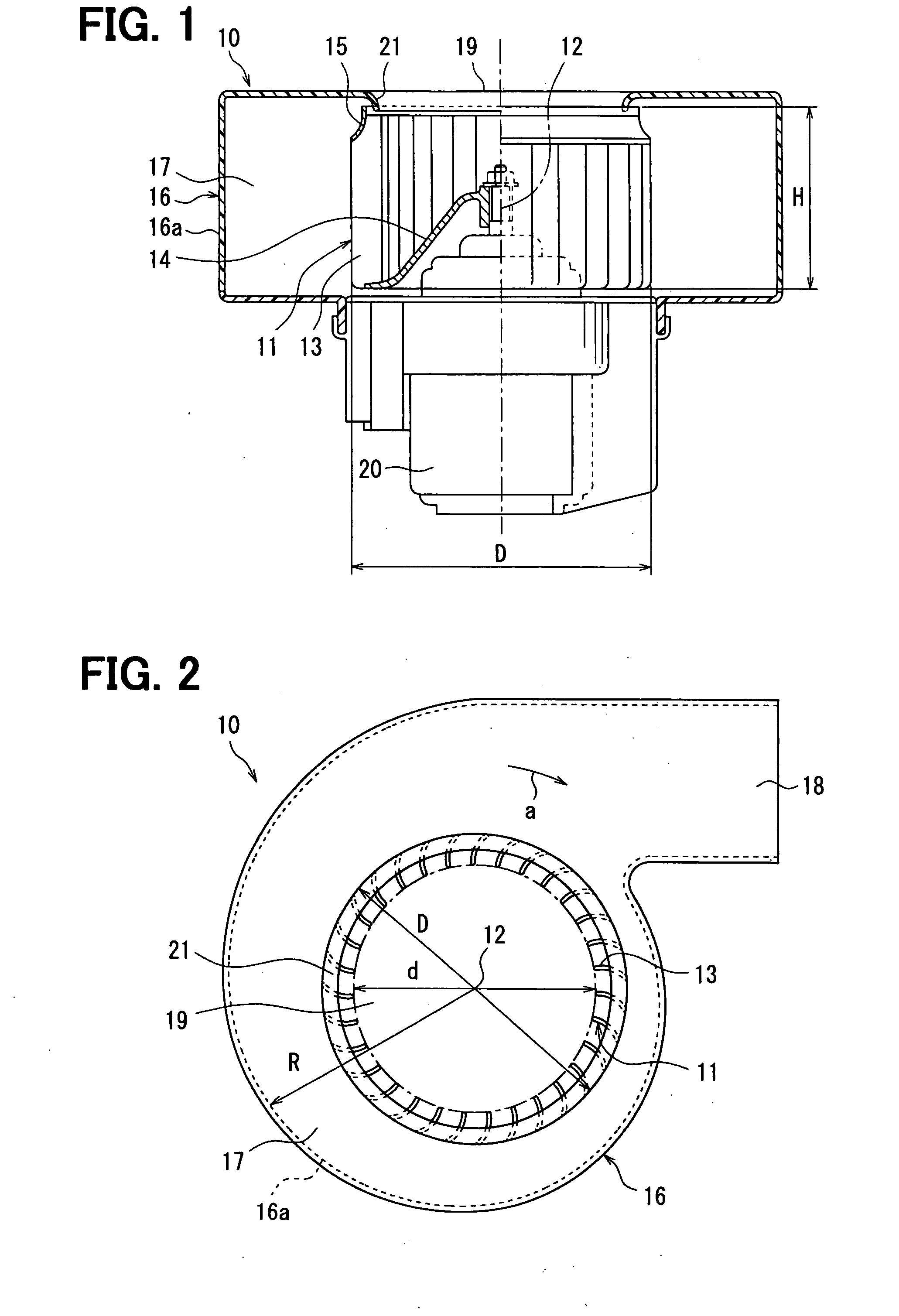
[0031]A first embodiment of the invention is described with reference to FIGS. 1-8. A blower 10 including a centrifugal multiblade fan according to a first embodiment of the invention is typically used for a vehicular air conditioner. FIG. 1 is a cross sectional view of a blower 10 including the centrifugal multiblade fan 11 according to the invention. FIG. 2 is a front view of the blower 10.
[0032]The centrifugal multiblade fan (hereafter abbreviated as a fan) 11 according to the invention includes a plurality of blades (wings) 13 around a rotation axis (a center line in FIG. 1) 12 and a holding plate (a boss) 14 holding the blades 13. The fan 11 sucks an air from one end side of an axial direction of the rotation axis 12 to a radial inside, and blows the air to a radial outside.
[0033]At a suction side (i.e., the one end side of the axial direction of the rotation axis 12) of the fan 11, shrouds 15 formed into a short circular arc shape in cross section are provided so that height H...
second embodiment
[0072]In the above-described first embodiment, the first angle part 22a and the second angle part 22b are formed separately from each other at the leading edge 22 of each blade 13. However, in the second embodiment, as shown in FIG. 9, the first angle part 22a and the second angle part 22b are not formed at the leading edge 22, and the leading edge 22 is formed into a sharply peaked shape.
[0073]In addition, in the second embodiment, the third angle part 25a and the fourth angle part 25b of the first embodiment are not formed at the trailing edge 25 of each blade 13, and the trailing edge 25 is also formed into a sharply peaked shape.
[0074]In the second embodiment, because the leading edge 22 is formed into a sharply peaked shape, the airflow always separates at the leading edge 22. Therefore, effects similar to the first embodiment can be obtained.
[0075]In addition, in the second embodiment, the blade thickness on the side of the leading edge 22 and the side of the trailing edge 25 ...
third embodiment
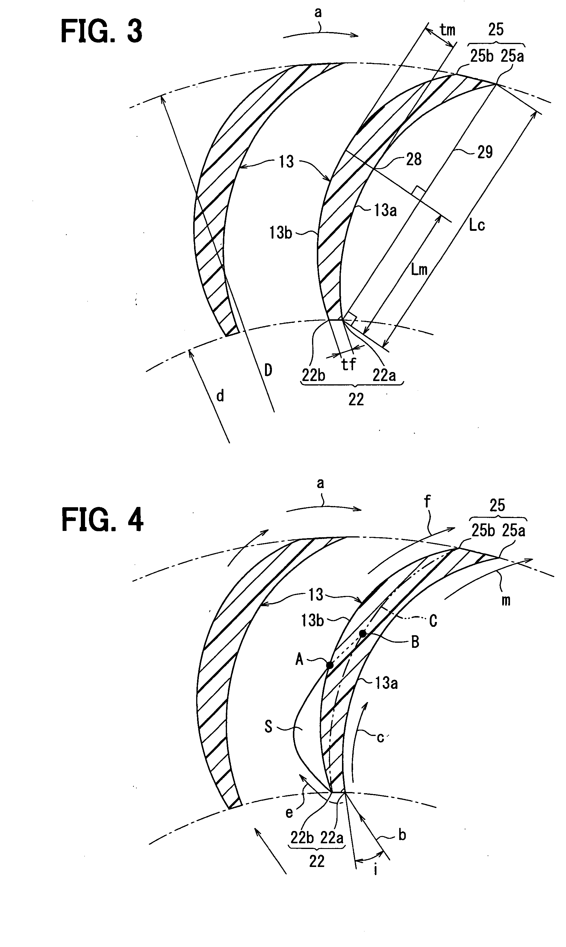
[0077]In the above-described first embodiment, the blade thickness of each blade 13 is increased gradually from both the leading edge 22 and the trailing edge 25 to the thickness portion 28 in the chordwise direction. However, in the third embodiment, the blade thickness is substantially constant in the chordwise direction as shown in FIG. 10.
[0078]Although, in the third embodiment, the trailing edge 25 of each blade 13 is formed into a smooth curved shape in cross section, the third angle part 25a and the fourth angle part 25b may be formed separately at the trailing edge 25 like the first embodiment.
[0079]In the third embodiment, because the second angle part 22b is formed into the edge shape, the airflow can always separate at the second angle part 22b. The separated airflow reattaches to each blade 13 at a reattachment point E, and the separation area S of the airflow is formed on the side of the back surface 13b of each blade 13.
[0080]In FIG. 10, the comparative example 2 is sh...
PUM
 Abstract
Description
Claims
Application Information