
Centrifugal multiblade fan

a multi-blade fan and centrifugal technology, applied in the direction of liquid fuel engines, marine propulsion, vessel construction, etc., can solve the problems of reducing causing noise generation, so as to improve the efficiency of the fan, prevent the fluctuation of the separation point and the reattachment point, and improve the effect of airflow

Active Publication Date: 2011-09-06
DENSO CORP
View PDF17 Cites 9 Cited by
  • Summary
  • Abstract
  • Description
  • Claims
  • Application Information

AI Technical Summary

Benefits of technology

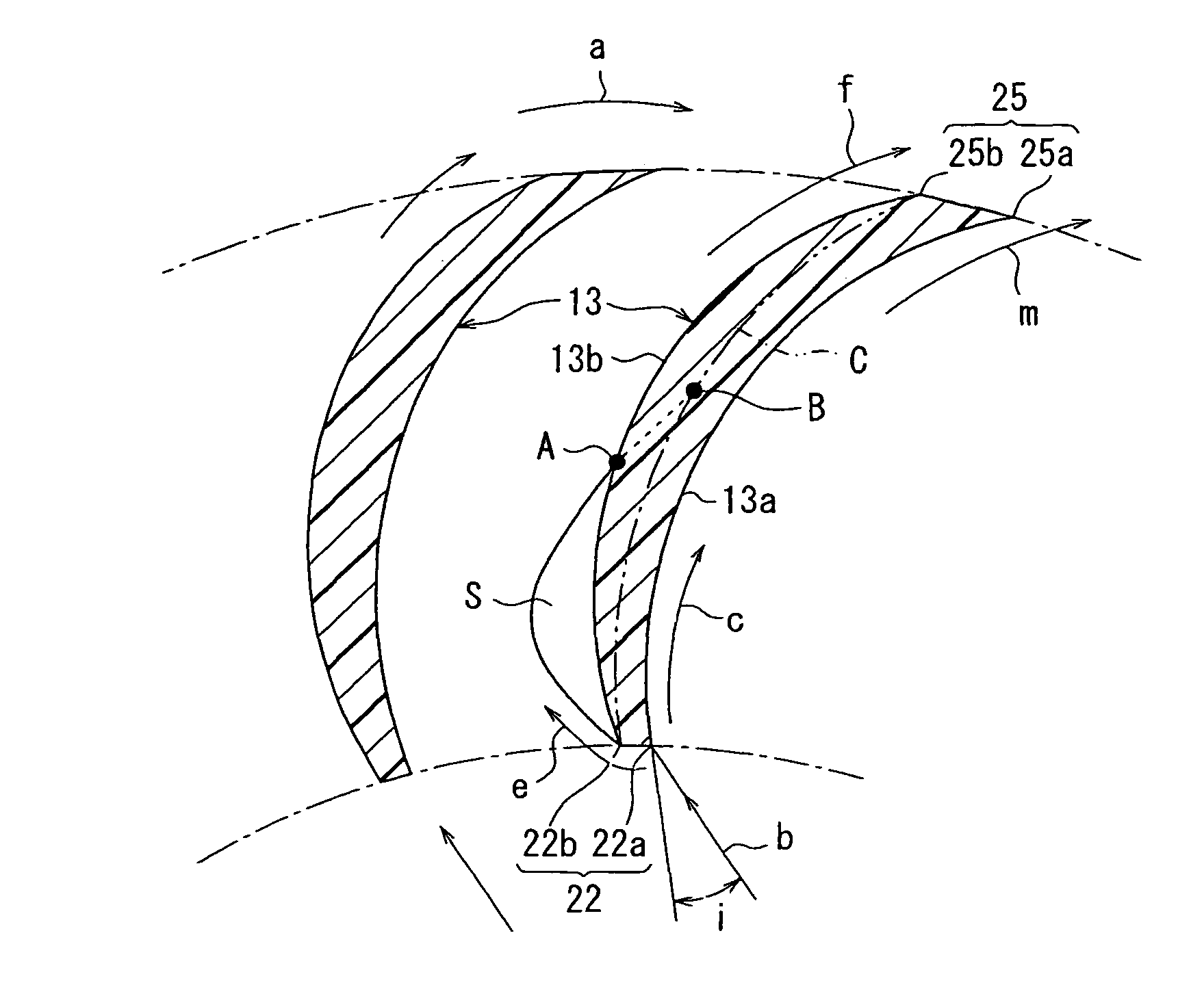
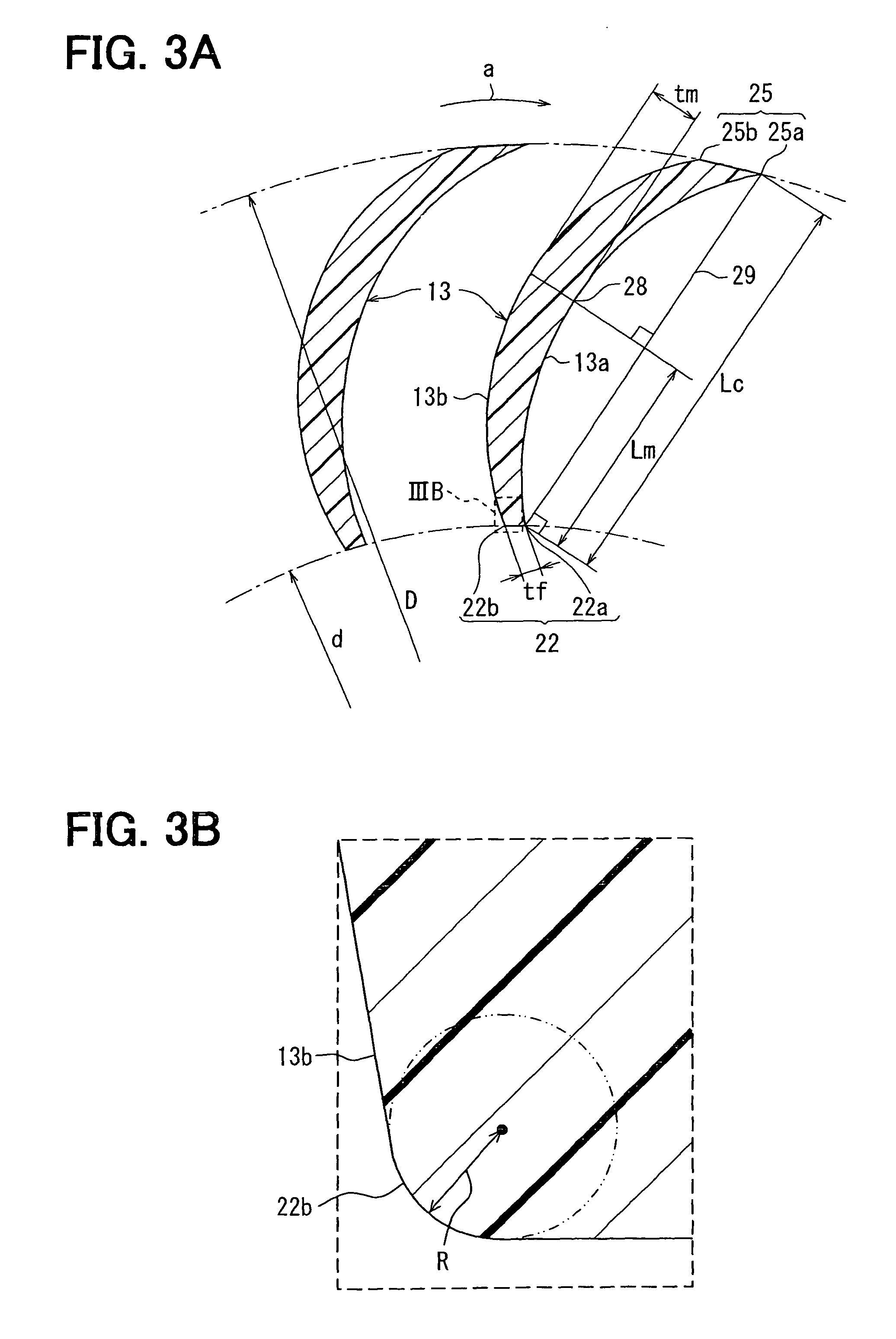
The present invention provides a centrifugal multiblade fan with improved fan efficiency and reduced noise. The fan includes a plurality of blades located around the rotation axis, with each blade having a leading edge and a trailing edge. The leading edge has an edge shape with a radius of curvature of 0.2 mm or less, which prevents fluctuations in the separation point and reattachment point, and restricts airflow between the blades. The second angle part of the blade has an edge shape, which increases the distance that the airflow can be rectified between the blades on the trailing edge side. This results in stable airflow and improved fan efficiency. The leading edge of the blade has an edge-shaped part that always separates the air from the one end side of the axial direction of the rotation axis, preventing fluctuations in the separation point and reattachment point. The distance that the airflow can be rectified between the blades on the trailing edge side increases, resulting in stable airflow and reduced noise.

Problems solved by technology

Conventionally, in this kind of the centrifugal multiblade fan, a leading edge (an edge on the rotation axis side) of each blade is formed into a smooth curved shape in cross section to reduce a separation of airflow at the leading edge on some level, and reduces a fan efficiency reduction and a noise generation caused by the separation.
Therefore, the airflow between the blades becomes unstable.
As a result, the fan efficiency is reduced and the noise is generated.
Furthermore, the tumor is difficult to be completely the same shape as that of the separation area of the airflow.
Therefore, the space where the separation of the airflow generates cannot be reduced enough.

Method used


Image

  • Centrifugal multiblade fan
  • Centrifugal multiblade fan
  • Centrifugal multiblade fan

Examples


first embodiment

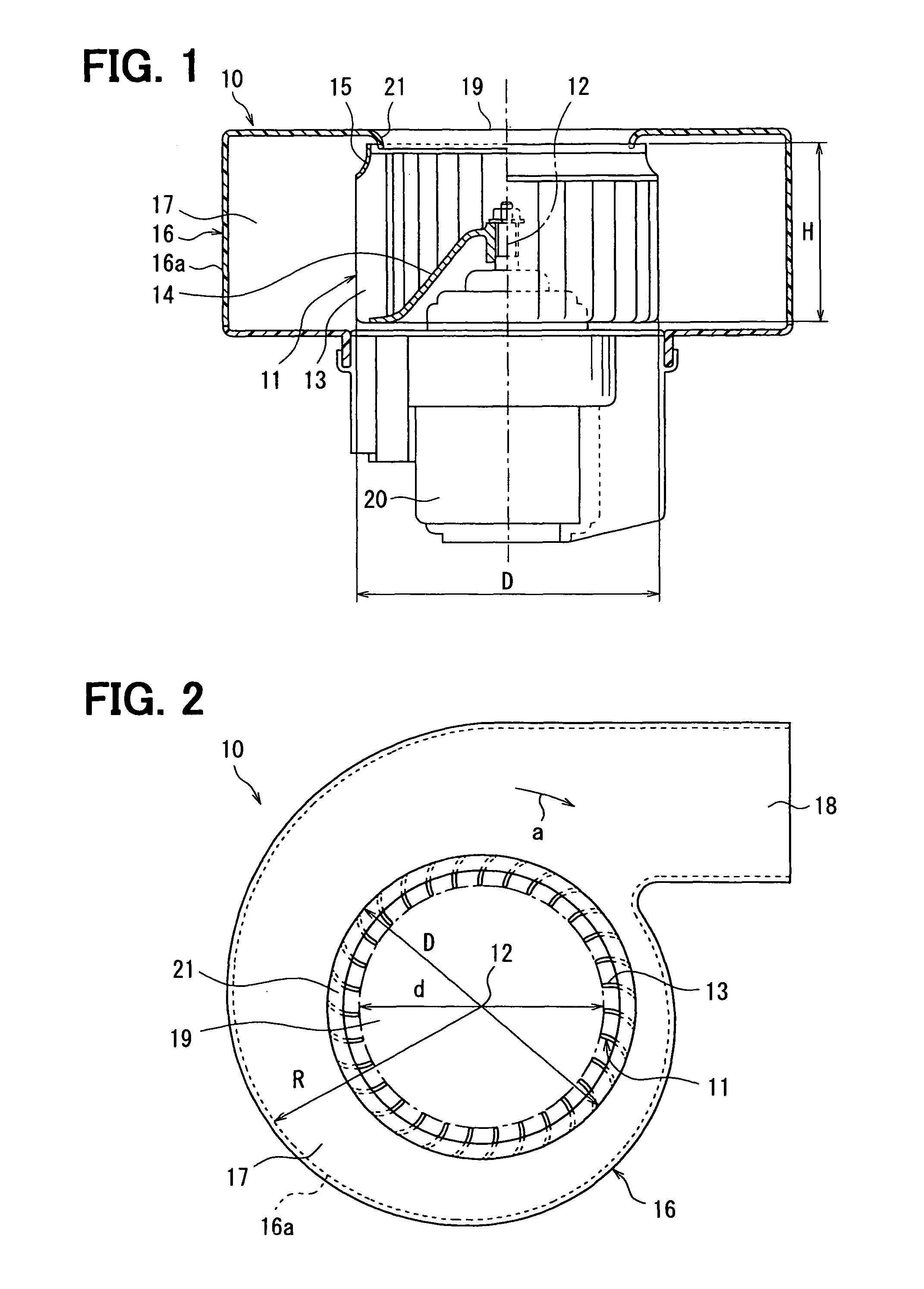
[0032]A first embodiment of the invention is described with reference to FIGS. 1-8. A blower 10 including a centrifugal multiblade fan according to a first embodiment of the invention is typically used for a vehicular air conditioner. FIG. 1 is a cross sectional view of a blower 10 including the centrifugal multiblade fan 11 according to the invention. FIG. 2 is a front view of the blower 10.

[0033]The centrifugal multiblade fan (hereafter abbreviated as a fan) 11 according to the invention includes a plurality of blades (wings) 13 around a rotation axis (a center line in FIG. 1) 12 and a holding plate (a boss) 14 holding the blades 13. The fan 11 sucks an air from one end side of an axial direction of the rotation axis 12 to a radial inside, and blows the air to a radial outside.

[0034]At a suction side (i.e., the one end side of the axial direction of the rotation axis 12) of the fan 11, shrouds 15 formed into a short circular arc shape in cross section are provided so that height H...

second embodiment

[0073]In the above-described first embodiment, the first angle part 22a and the second angle part 22b are formed separately from each other at the leading edge 22 of each blade 13. However, in the second embodiment, as shown in FIG. 9, the first angle part 22a and the second angle part 22b are not formed at the leading edge 22, and the leading edge 22 is formed into a sharply peaked shape.

[0074]In addition, in the second embodiment, the third angle part 25a and the fourth angle part 25b of the first embodiment are not formed at the trailing edge 25 of each blade 13, and the trailing edge 25 is also formed into a sharply peaked shape.

[0075]In the second embodiment, because the leading edge 22 is formed into a sharply peaked shape, the airflow always separates at the leading edge 22. Therefore, effects similar to the first embodiment can be obtained.

[0076]In addition, in the second embodiment, the blade thickness on the side of the leading edge 22 and the side of the trailing edge 25 ...

third embodiment

[0078]In the above-described first embodiment, the blade thickness of each blade 13 is increased gradually from both the leading edge 22 and the trailing edge 25 to the thickness portion 28 in the chordwise direction. However, in the third embodiment, the blade thickness is substantially constant in the chordwise direction as shown in FIG. 10.

[0079]Although, in the third embodiment, the trailing edge 25 of each blade 13 is formed into a smooth curved shape in cross section, the third angle part 25a and the fourth angle part 25b may be formed separately at the trailing edge 25 like the first embodiment.

[0080]In the third embodiment, because the second angle part 22b is formed into the edge shape, the airflow can always separate at the second angle part 22b. The separated airflow reattaches to each blade 13 at a reattachment point E, and the separation area S of the airflow is formed on the side of the back surface 13b of each blade 13.

[0081]In FIG. 10, the comparative example 2 is sh...


PUM


Abstract

A centrifugal multiblade fan according to the present invention sucks air from one end side of an axial direction of a rotation axis to a radial inside, and blows the air to a radial outside. The centrifugal multiblade fan includes a plurality of blades located around the rotation axis. Each blade has a leading edge positioned at the radial inside, and a trailing edge positioned at a radial outside. The leading edge of each blade has an edge shape with a radius of curvature of 0.2 mm or less, for example.

Description

CROSS REFERENCE TO RELATED APPLICATION[0001]This application is based on Japanese Patent Applications No. 2006-70383 filed on Mar. 15, 2006 and No. 2006-283711 filed on Oct. 18, 2006, the contents of which are incorporated herein by reference in its entirety.BACKGROUND OF THE INVENTION[0002]1. Field of the Invention[0003]The present invention relates to a centrifugal multiblade fan which includes a plurality of blades located around a rotation axis.[0004]2. Description of the Related Art[0005]Conventionally, in this kind of the centrifugal multiblade fan, a leading edge (an edge on the rotation axis side) of each blade is formed into a smooth curved shape in cross section to reduce a separation of airflow at the leading edge on some level, and reduces a fan efficiency reduction and a noise generation caused by the separation.[0006]However, when the leading edge of each blade is formed into the smooth curved shape in cross section, a point where the airflow separates and a point wher...

Claims


Application Information

Patent Timeline
Patent Type & Authority Patents(United States)
IPC IPC(8): F04D29/28
CPCF04D29/282
Inventor OCHIAI, TOSHINORISAKAI, MASAHARUSEKI, HIDEKI
Owner DENSO CORP
Learn More