
Drying barrel structure for spinning

A drying barrel and drying box technology, applied in drying, drying machine, drying solid materials and other directions, can solve the problems of user loss, reduce drying effect, waste of resources, etc., achieve convenient installation, increase drying Efficiency, the effect of increasing drying uniformity

Inactive Publication Date: 2015-09-23
周盈裕
View PDF10 Cites 4 Cited by
  • Summary
  • Abstract
  • Description
  • Claims
  • Application Information

AI Technical Summary

Problems solved by technology

[0002] As we all know, the dryer plays a decisive role in the production of textiles. As an indispensable equipment, the quality of the dryer will directly affect the quality of the textile. The existing dryer mainly includes a drying box and a The heating device inside the drying box, the heating device heats up to make the temperature in the drying box meet the specification requirements and then dries the cloth in the drying box. Steam, these water vapors often cause the fabric to be wet again, so it is necessary to clean up the water vapor in the oven in time, and the excessive accumulation of water vapor will also reduce the drying effect and cause a waste of resources, which will bring great harm to the user. to a certain loss

Method used


Image

  • Drying barrel structure for spinning
  • Drying barrel structure for spinning

Examples


Embodiment Construction

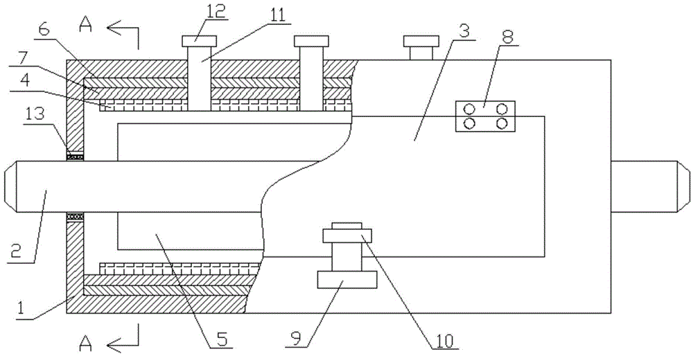
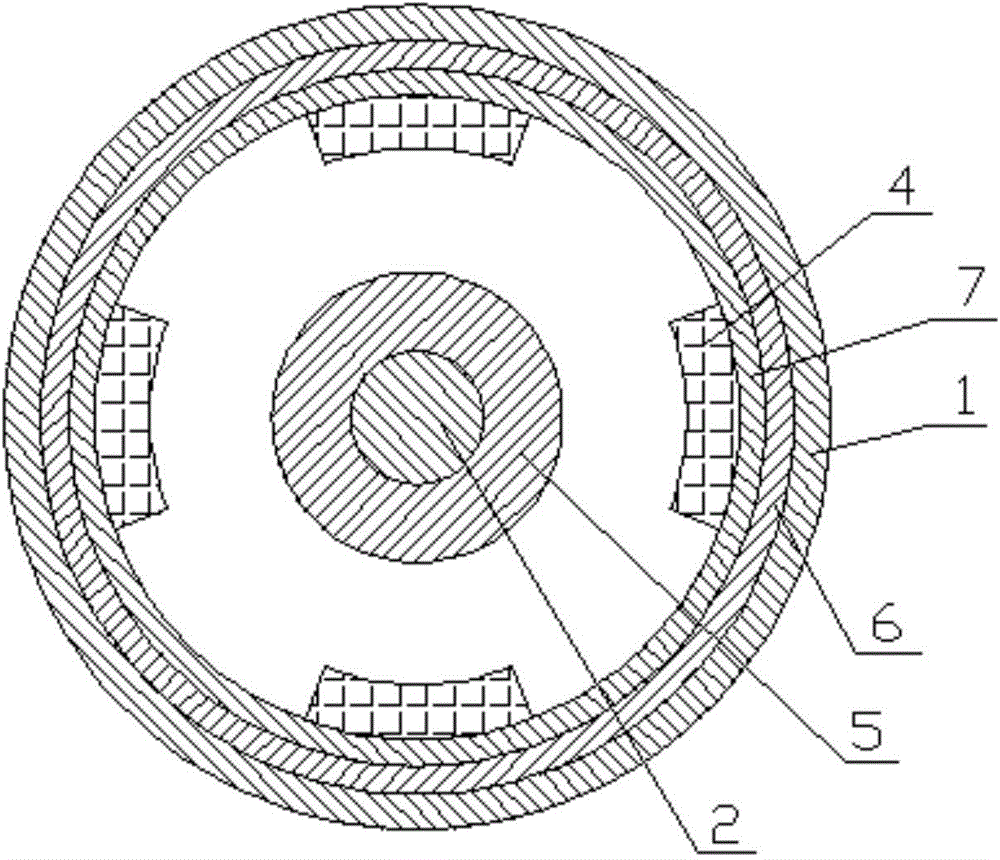
[0013] refer to figure 1 with figure 2 The shown structure of a drying barrel for textiles includes a drying barrel body 1, a rotating shaft 2 arranged on the drying barrel body 1, a door 3 arranged on the drying box body 1, and a The dryer 4 on the drying box body 1, the rotating shaft 2 is set through the drying box body 1, and the rotating shaft 2 in the drying oven body 1 is sleeved with a drum 5 that can wrap textiles. The inner wall of the drying barrel body 1 is provided with a drying film 6, and an insulating layer 7 is arranged on the outer surface of the drying film 6. The dryer 4 is arranged on the drying barrel equipped with the drying film 6 and the insulating layer 7. On the inner wall of the body 1, a living hinge 8 is provided on the drying barrel body 1, the box door 3 is hinged on the living hinge 8, and a first buckle 9 is provided on the drying barrel body 1 , A second buckle 10 matched with the first buckle 9 is provided on the box door 3, and three air...


PUM


Abstract

The invention discloses a drying barrel structure for spinning. The drying barrel structure comprises a drying barrel body, a rotating shaft arranged on the drying barrel body, a barrel door arranged on the drying barrel body and drying apparatuses arranged on the drying barrel body. The rotating shaft is arranged in a manner of penetrating the drying barrel body, and the rotating shaft in the drying barrel body is sleeved with a drum capable of winding fabric; a drying thin film is arranged on the inner wall of the drying barrel body, and a heat preservation layer is arranged on the outer surface of the drying thin film; the drying apparatuses are arranged on the inner wall, equipped with the drying thin film and the heat preservation layer, of the drying barrel body, and a movable hinge is arranged on the drying barrel body; the barrel door is hinged to the movable hinge; a first clamping buckle is arranged on the drying barrel body, and a second clamping buckle matched with the first clamping buckle is arranged on the barrel door; and three air outlet pipelines for facilitating exhausting of wet gas are arranged on the upper portion of the drying barrel body. The drying barrel structure is simple in structure, convenient to use and mount, good in drying effect, uniform in drying, low in energy consumption, low in cost and long in service life, saves labor and has the safe and reliable effects, and the fabric can be conveniently put and taken.

Description

technical field [0001] The invention relates to a drying barrel structure for weaving. Background technique [0002] As we all know, the dryer plays a decisive role in the production of textiles. As an indispensable equipment, the quality of the dryer will directly affect the quality of the textile. The existing dryer mainly includes a drying box and a The heating device inside the drying box, the heating device heats up to make the temperature in the drying box meet the specification requirements and then dries the cloth in the drying box. Steam, these water vapors often cause the fabric to be wet again, so it is necessary to clean up the water vapor in the oven in time, and the excessive accumulation of water vapor will also reduce the drying effect and cause a waste of resources, which will bring great harm to the user. To a certain loss. Contents of the invention [0003] The technical problem to be solved by the present invention is to provide a simple structure, ea...

Claims


Application Information

Patent Timeline
Patent Type & Authority Applications(China)
IPC IPC(8): F26B11/04F26B25/00
Inventor 周盈裕
Owner 周盈裕
Learn More