Time-based sheet forming limit determination method

A method for determining the forming limit and a technology for determining the forming limit, which is applied in the field of time-based determination of the forming limit of thin plates, which can solve the problems such as the failure to accurately control the stop of the sample, the failure of the rupture point to fully reflect the in-situ deformation of the inspection point, and the inability to truly determine the limit strain.

Active Publication Date: 2015-09-23
SHOUGANG CORPORATION
View PDF5 Cites 10 Cited by
  • Summary
  • Abstract
  • Description
  • Claims
  • Application Information

AI Technical Summary

Problems solved by technology

The disadvantage of this method is that the sample has been broken, the punch cannot stop when it just breaks, and it cannot accurately control the stop of the sample when it just appears necking, so it is impossible to truly determine the ultimate str...

Method used


Image

  • Time-based sheet forming limit determination method
  • Time-based sheet forming limit determination method
  • Time-based sheet forming limit determination method

Examples


Embodiment 1

[0017] see figure 2 , a time-based thin plate forming limit determination method provided by an embodiment of the present invention includes:

[0018] Step 110: set up a steel ball mold bulging test;

[0019] Step 120: Carry out the steel ball mold bulging test to the plate, and take pictures of the bulging sample until the plate breaks;

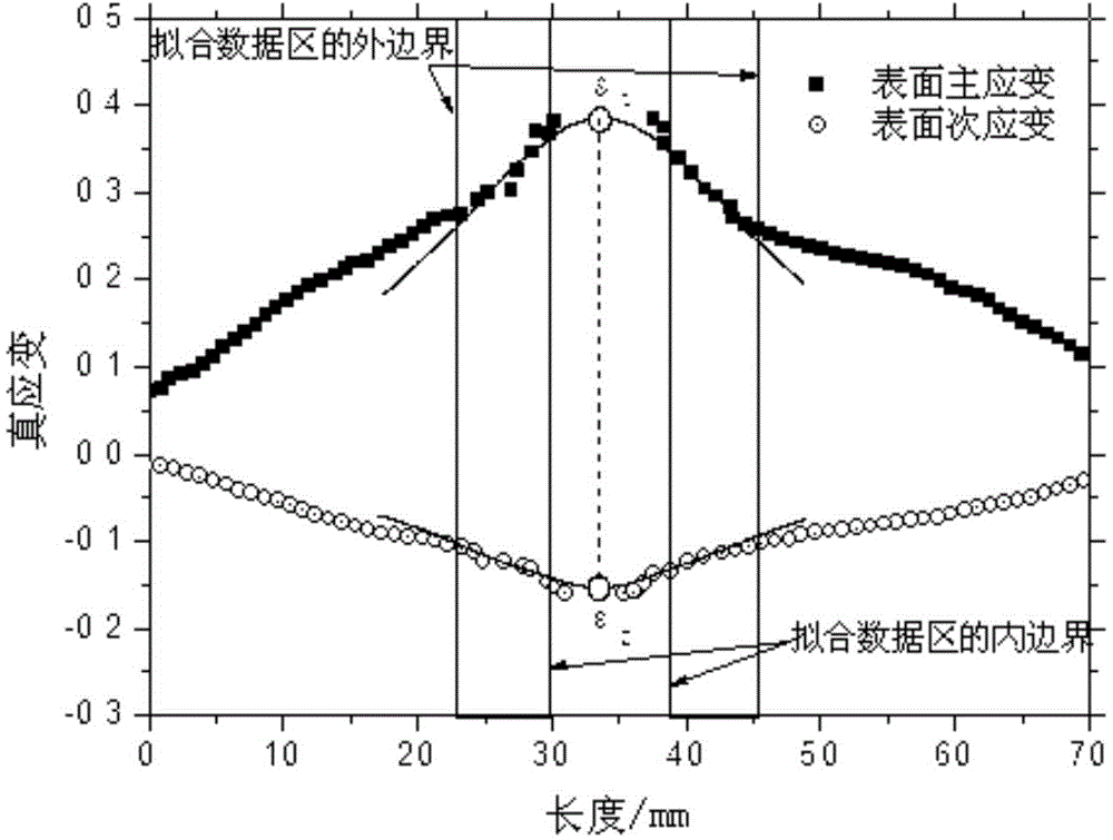
[0020] Step 130: Obtain the previous frame image of the sample just cracking according to the photograph taken, take the cracking point as the center, select an area near the cracking point as the investigation area;

[0021] Step 140: obtain the surface principal strain average value and the surface secondary strain average value of the investigation area;

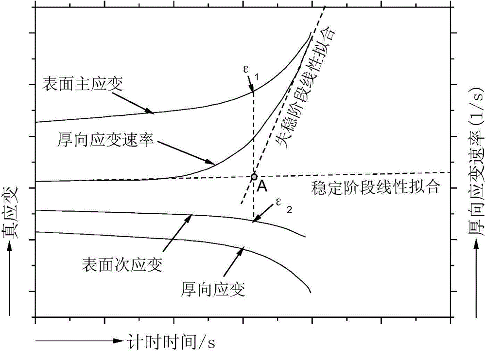
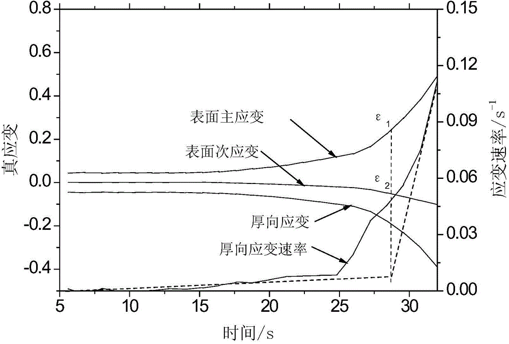
[0022] Step 150: According to the principle of constant volume, calculate the principal strain in the thickness direction and the strain rate in the thickness direction;

[0023] Step 160: Obtain the data of the stable stage and the unstable stage according to the thickness strain r...

Embodiment 2

[0037] In order to introduce the embodiment of the present invention more clearly, the following will introduce it from the specific examples of the embodiment of the present invention.

specific Embodiment 1

[0038] The steel ball die bulging in GB / T 15825.8-2008 Forming Limit Diagram Determination Method is used for the test, and a high-frequency camera is used to take pictures of the bulging sample until the material breaks. The image collection of each sample during the deformation process is not less than 50 photos, and the image collection can also be concentrated in the late stage of sample deformation, in order to increase the sampling frequency of the sample at the end of deformation.

[0039] Find out the position of the sample rupture point, and retrieve the image in reverse order of time to obtain the previous frame image of the sample just before the rupture point, and select several areas close to the rupture point with the rupture point as the center. The number of selected areas depends on the resolution of the camera and the electronic grid size of the software.

[0040] For each photo, use the strain analysis software to analyze the average value of the surface pri...


PUM


Abstract

The invention discloses a time-based sheet forming limit determination method and belongs to the technical field of stamping processes. The time-based sheet forming limit determination method comprises the following steps: establishing a steel ball die bulging test; performing the steel ball die bulging test on a sheet material, and shooting a bulging sample until the sheet material is broken; obtaining a previous frame of image of the sample which is just broken according to a shot photo, taking a breaking point as a center, and selecting a region near the part close to the breaking point as an inspection region; obtaining primary and secondary surface strain mean values of the inspection region; performing calculation to obtain primary thickness direction strain and thickness direction strain rate; and obtaining data at stable and instable stages according to the thickness direction strain rate, and comparing the data at stable and instable stages to obtain a forming limit point. The time-based sheet forming limit determination method is capable of really determining limit strain of just happened tightening or cracking to fully reflect in-situ deformation situation of an inspection point.

Description

technical field [0001] The invention relates to the technical field of stamping technology, in particular to a method for determining the forming limit of a thin plate based on time. Background technique [0002] The forming limit diagram is widely used to judge the necking or cracking of the sheet metal during the forming process, and it is especially important in the practical application of the sheet metal forming process. At present, the most commonly used method to determine the forming limit curve is to use the Erichsen steel ball die bulging test. When the sample cracks, the loading is stopped immediately, and the curve fitting is performed on the primary and secondary strain profiles throughout the sample section, as shown in figure 1 As shown, find the strain value corresponding to the highest point of the fitting curve as the forming limit strain. The disadvantage of this method is that the sample has already broken, and the punch cannot stop when it just breaks, ...

Claims


Application Information

Patent Timeline
IPC IPC(8): G01N3/00
Inventor 邝霜韩赟刘华赛姜英花朱国森王勇围齐秀美刘广会
Owner SHOUGANG CORPORATION
Why Eureka
Try Eureka