In-fiber optical whispering gallery microcavity structure and its manufacturing method

A kind of whispering gallery, optical technology, applied in manufacturing tools, laser welding equipment, coupling of optical waveguides, etc., can solve the problem of difficult to achieve miniaturization, integration, low system compactness and stability, complex microsphere filling process The problem is to reduce the difficulty of positioning, accurately adjust the size parameters, and simplify the processing method.

Active Publication Date: 2017-10-20
CHONGQING UNIV
View PDF4 Cites 0 Cited by
  • Summary
  • Abstract
  • Description
  • Claims
  • Application Information

AI Technical Summary

Problems solved by technology

[0003] At present, microcavities that can form optical whispering gallery modes include structures such as microspheres, microdisks, and microrings. These resonant cavity structures are generally produced by mechanical grinding and surface tension; among them, the resonant cavity produced by mechanical grinding is due to Limited by the technical conditions of the mechanical grinding process, the size of the resonant cavity is large, and it is difficult to realize miniaturization and integration; in addition, the whispering gallery mode of the passive microcavity is generally excited by three ways: prism, polished fiber and tapered fiber, Prisms and polished fibers are less efficient at exciting whispering gallery modes than tapered fibers, but the diameter of tapered fibers is required to be less than 2 microns and tapered fibers are susceptible to pollution and air disturbances, and the above three systems for exciting optical whispering gallery modes are all are separated, so the overall system is less compact and less stable
[0004] The research on the integration of optical whispering gallery and microcavity is an inevitable requirement for its practical application. Optical echo can be realized by filling microspheres of various materials in structures such as microfibers, corroded photonic crystal fibers, and corroded ultra-thin-walled capillaries. wall microcavity, but the filling process of microspheres is very complex and selective to the size of the balls. Finding a highly integrated and simple manufacturing method is an important problem in the field of optical whispering gallery microcavities.

Method used


Image

  • In-fiber optical whispering gallery microcavity structure and its manufacturing method

Examples


Embodiment Construction

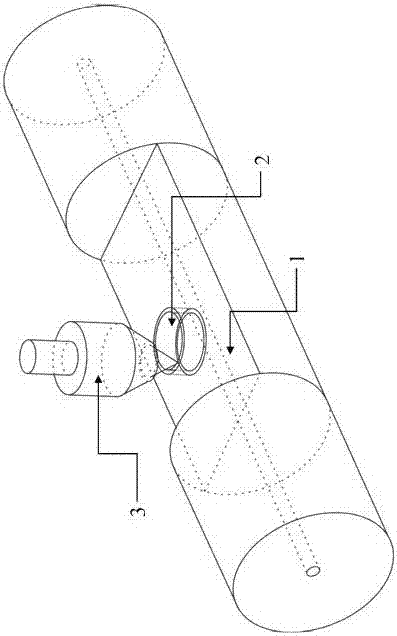
[0018] A fiber-type optical whispering gallery microcavity structure, including an optical fiber, its innovation lies in: an annular groove is arranged on the outer side of the fiber core on the optical fiber, the axial direction of the annular groove is parallel to the radial direction of the optical fiber, and the outer wall of the annular groove is parallel to the optical fiber. Spaces are left between the outer walls of the fiber core, and the depth of the annular groove covers the fiber core of the optical fiber, and the annular groove forms an optical whispering gallery microcavity.

[0019] A method for manufacturing a fiber-shaped optical whispering gallery microcavity structure, the innovation of which is: fabricating a fiber-shaped optical whispering gallery microcavity structure according to the following method:

[0020] 1) Use a femtosecond laser to cut the surface of the optical fiber, and cut a processed surface outside the core of the optical fiber. The processe...


PUM


Abstract

Provided is an in-fiber type optical echo wall micro-cavity structure, comprising a fiber, and characterized in that the outside of the fiber core on the fiber is provided with an annular groove; the axial direction of the annular groove is parallel with the radial direction of the fiber; a gap is left between the outer wall of the annular groove and the outer wall of the fiber core; the annular groove is deep enough to cover the fiber core of the fiber; the annular groove forms an optical echo wall micro-cavity. The technical effects are that the echo wall micro-cavity is embedded in the fiber, and has a stable structure; the echo wall micro-cavity and a stimulation part form a whole structure, and are highly integrated; the processing method of the echo wall micro-cavity is simple, and dimension parameters are accurate and adjustable.

Description

technical field [0001] The invention relates to an optical fiber sensing technology, in particular to an in-fiber optical whispering gallery microcavity structure and a manufacturing method thereof. Background technique [0002] The optical whispering gallery microcavity confines light in the resonant cavity through continuous total reflection at the boundary of the dielectric cavity, and has the characteristics of ultra-high quality factor and ultra-small mode volume. Ultra-low threshold lasers and other fields have important application prospects. [0003] At present, microcavities that can form optical whispering gallery modes include structures such as microspheres, microdisks, and microrings. These resonant cavity structures are generally produced by mechanical grinding and surface tension; among them, the resonant cavity produced by mechanical grinding is due to Limited by the technical conditions of the mechanical grinding process, the size of the resonant cavity is ...

Claims


Application Information

Patent Timeline
Patent Type & Authority Patents(China)
IPC IPC(8): G02B6/24B23K26/38
CPCB23K26/38G02B6/24
Inventor 朱涛史磊磊
Owner CHONGQING UNIV
Why Eureka
Try Eureka