Thread guide unit for textile machine

A textile machine and yarn guide technology, which is applied in the direction of conveying filamentous materials, thin material processing, transportation and packaging, etc., can solve the problems of expensive, increased installation and maintenance costs of yarn guide units, etc., to reduce inertia and benefit Installation and maintenance costs, effects of improved controllability

Active Publication Date: 2015-09-23
SSM萨罗瑞士麦特雷有限公司
View PDF9 Cites 5 Cited by
  • Summary
  • Abstract
  • Description
  • Claims
  • Application Information

AI Technical Summary

Problems solved by technology

[0006] Such pulleys are significantly more expensive in their manufacture than pulleys with only one flanged disc, but in said pulleys with only one flanged disc, so-called belt guide plates must additionally be used in order to ensure that the drive belt does not slip off the pulley
The belt guide plates have to be adjusted individually, which in practice unduly increases the installation and maintenance costs of the yarn guide unit

Method used


Image

  • Thread guide unit for textile machine
  • Thread guide unit for textile machine

Examples


Embodiment Construction

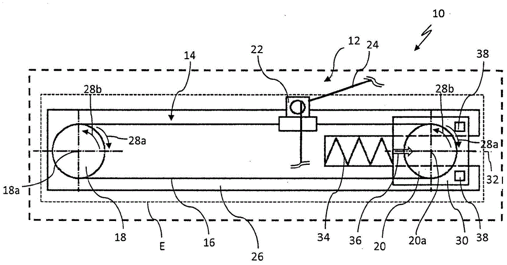
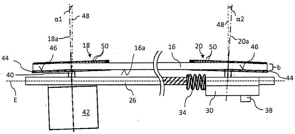
[0026] figure 1 A textile machine 10 is shown with a thread guide unit 12 . The textile machine 10 is only shown schematically for reasons of graphic representation and can be designed, for example, as a winder or texturing machine. The thread guide unit 12 has a belt drive 14 with a drive belt 16 which is wound around a first pulley 18 and a second pulley 20 . The drive belt 16 is currently implemented as a continuous belt. Drive belt 16 forms a belt with its two return sections figure 1 The belt plane indicated by the dotted line in , which is indicated by the reference character "E". A yarn guide 22 for guiding a yarn 24 is fixed on the drive belt 16 . The two belt pulleys 18 , 20 are mounted rotatably about their respective axes of rotation 18 a , 20 a relative to the support element 26 of the thread guide unit 12 in mutually opposite directions of rotation 28 a , 28 b. The carrier element 26 is in the present case embodied, for example, as a carrier plate. The first...


PUM


Abstract

The thread guide unit has a thread guide that is configured for feeding a thread. A belt drive is provided with a drive belt (16) at which the thread guide is secured, with the pulleys (18,20). A steering wheel and controllable drive motor (42) configured for driving two pulleys. The pulleys for the lateral guide of the drive belt are provided with a flanged wheel (44). The pulleys with rotational axes (18a,20a) is arranged relative to a solder (48) of a belt plane such that drive belt is fed in the side edge (16a) against the flanged wheels.

Description

technical field [0001] The invention relates to a yarn guide unit for a textile machine. Background technique [0002] In practice, yarn guide units have long been used in spinning machines in order to move the yarn back and forth in rapid succession during winding or rewinding of the yarn. For this back-and-forth movement, a thread-guiding unit with a belt drive is usually used. The belt drive here comprises a drive belt to which the thread guide can be fastened directly. In the simplest case, the drive belt is guided around the first and second pulleys. Usually one of the two pulleys is configured as a drive pulley. The reciprocating movement of the yarn guide is produced by a series of correspondingly rapid changes in direction of the rotational movement of the drive pulley or of the drive motor assigned to the drive pulley. In particular, such a belt drive is characterized by a long service life and low maintenance costs due to its structurally simple design. This i...

Claims


Application Information

Patent Timeline
Patent Type & Authority Applications(China)
IPC IPC(8): B65H54/28
CPCB65H2701/31B65H54/2821
Inventor E·洛伊
Owner SSM萨罗瑞士麦特雷有限公司
Why Eureka
Try Eureka