Sealing device

A sealing device, lip technology, applied in the direction of engine sealing, transportation and packaging, bearings, etc., to achieve the effect of improving the sealing function

Active Publication Date: 2015-09-23
NOK CORP
View PDF8 Cites 3 Cited by
  • Summary
  • Abstract
  • Description
  • Claims
  • Application Information

AI Technical Summary

Problems solved by technology

[0004] However, in the above image 3 In the prior art, since the labyrinth lip 72 replaces the sliding lip 71 and is exposed to the foreign matter of the outside A, therefore, there is this labyrinth lip 72 that expands / deforms, and its function (by making the outside A It is difficult for foreign matter to reach the sliding lip 71 so as to protect the function of the sliding lip 71, hereinafter also referred to as "sliding lip protection function" or simply "function") risk of premature disappearance

Method used


Image

  • Sealing device
  • Sealing device
  • Sealing device

Examples


Embodiment

[0045] Embodiments of the present invention will be described below with reference to the drawings.

[0046] The sealing devices related to the various embodiments described below can be used as hub bearing seals (hub seals) in the bearing parts of automobile wheel suspension devices to prevent water and muddy water outside the bearing (outside the machine) A. , Salt water, dust, brake fluid or oil and other external foreign matter (interference factors) enter the bearing interior (machine) B, and at the same time, prevent the lubricating oil inside the bearing B from leaking to the bearing exterior A.

no. 1 example …

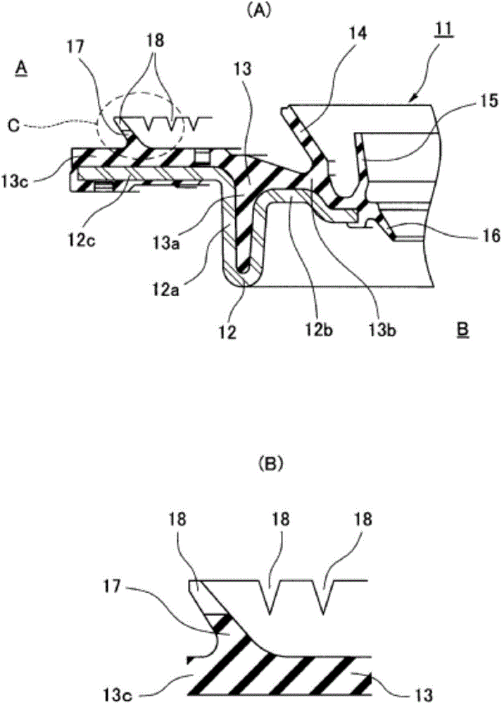
[0048] figure 1 The sealing device 11 shown in is provided with sliding lips 14, 15 for sealing so that foreign matter from the outside A does not enter the inside B of the machine, and a labyrinth lip that makes it difficult for foreign matter from the outside A to reach the sliding lips 14, 15. 17. Further, a notch 18 is provided at the front end of the labyrinth lip 17, and the notch 18 is used to absorb swelling when the labyrinth lip 17 is exposed to foreign matter A outside the machine and swells. The sliding lips 14 , 15 are arranged inside the machine of the labyrinth lip 17 , and the labyrinth lip 17 is arranged outside the machine of the sliding lips 14 , 15 .

[0049] The sealing device 11 is constituted by a metal ring (mounting ring) 12 and a rubber-like elastic body 13 covering (vulcanized and bonded) the metal ring 12 .

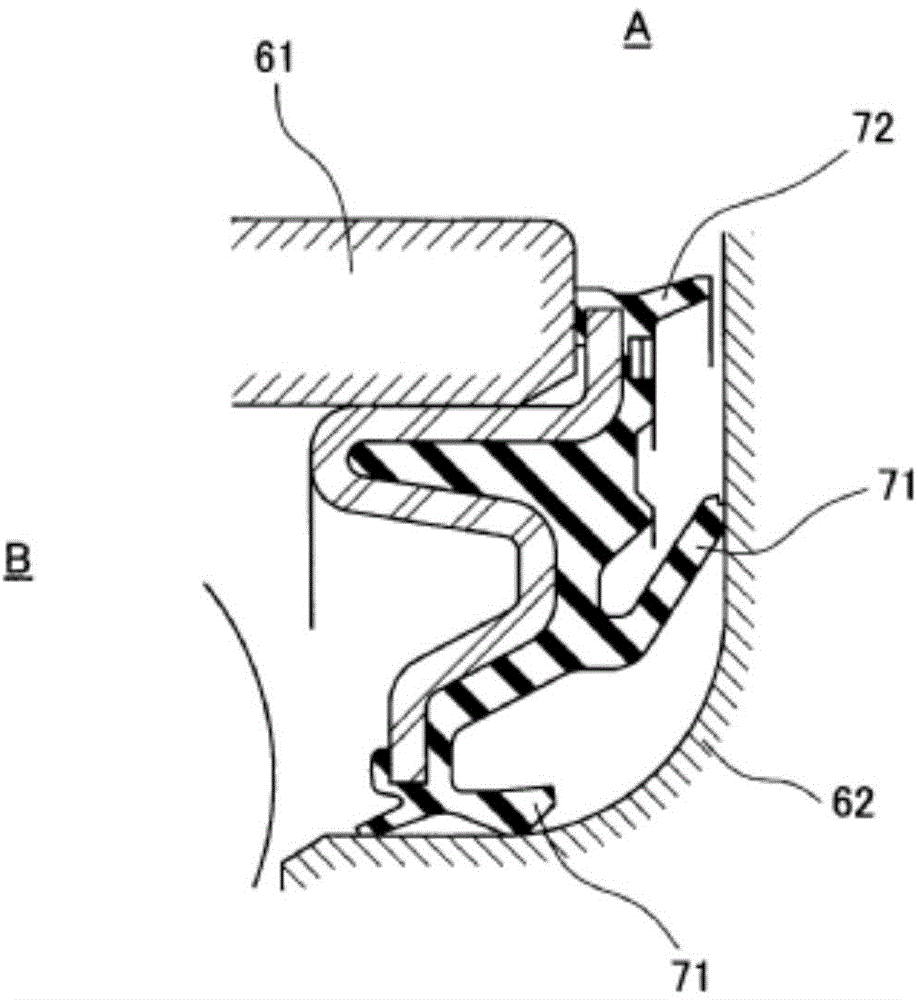
[0050] The ferrule 12 has an outer ring (housing) 61 (see image 3 ) on the inner peripheral surface of the cylindrical portion 12a, on the ...

no. 2 example …

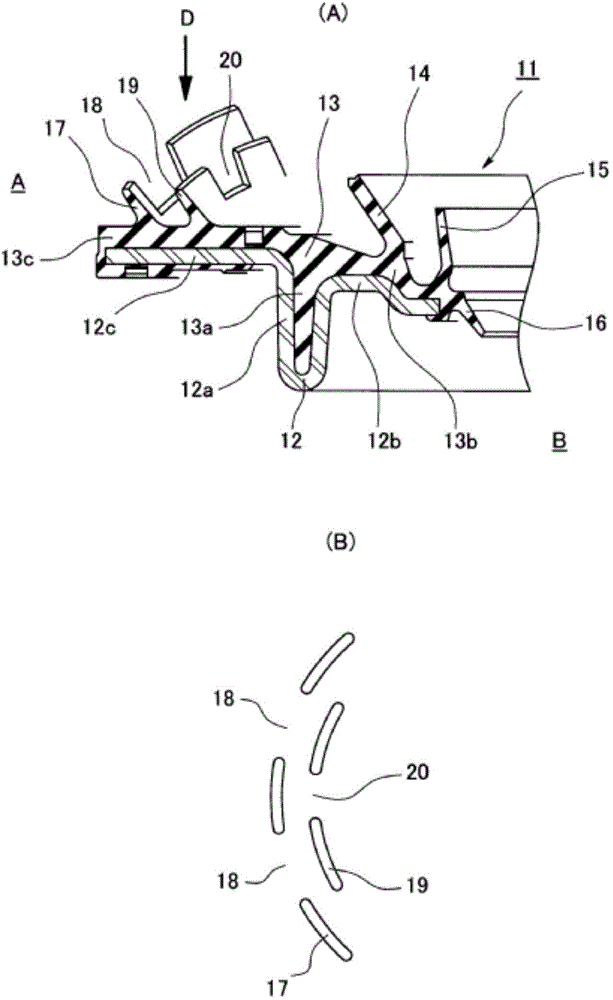
[0055] figure 2 The sealing device 11 shown in is provided with sliding lips 14, 15 for sealing so that foreign matter from the outside A does not enter the inside B of the machine, and a labyrinth lip that makes it difficult for foreign matter from the outside A to reach the sliding lips 14, 15. 17. Further, a notch 18 is provided at the front end of the labyrinth lip 17, and the notch 18 is used to absorb swelling when the labyrinth lip 17 is exposed to foreign matter A outside the machine and swells. also, figure 2 (A) is a sectional view of main parts of the sealing device 11, and also depicts a state (perspective view) overlooking the sliding lips 14 and 15 from obliquely above.

[0056] The sealing device 11 is constituted by a metal ring (mounting ring) 12 and a rubber-like elastic body 13 covering (vulcanized and bonded) the metal ring 12 .

[0057] The ferrule 12 has an outer ring (housing) 61 (see image 3 ) on the inner peripheral surface of the cylindrical port...


PUM


Abstract

Provided is a sealing device which comprises a sliding lip and a labyrinth lip, the sealing device being configured in such a manner that, even if the labyrinth lip is exposed to foreign matter outside a machine and swells, the deformation of the labyrinth lip is prevented and therefore the sliding lip-protecting function of the labyrinth lip is less likely to be lost. A sealing device is provided with: a sliding lip which performs sealing so that foreign matter outside a machine does not enter the inside of the machine; and a labyrinth lip which makes it less likely that foreign matter outside the machine reaches the sliding lip. The sealing device is characterized in that the front end of the labyrinth lip is provided with a cutout which absorbs the swelling of the labyrinth lip occurring when the labyrinth lip is exposed to foreign matter. Alternatively, the sealing device is characterized in that a second labyrinth lip is provided on the side of the labyrinth lip with which faces the inside of the machine. Alternatively, the sealing device is characterized in that a similar cutout is provided also in the front end of the second labyrinth lip.

Description

technical field [0001] The present invention relates to a sealing device, and more specifically, to a sealing device including a sliding lip and a labyrinth lip. The sealing device of the present invention is used, for example, as a hub bearing seal for vehicles such as automobiles, or as other bearing seals (including seals for industrial bearings). Background technique [0002] In existing hub bearing seals, when external foreign matter (disturbing factors) such as water, muddy water, salt water, dust, brake fluid, or oil adheres to the sealing lip of the hub bearing seal installed on the bearing, the lip is The rubber swells and deforms, thereby reducing the sealing performance of the lip, and thus, there is a disadvantage that foreign matter is more likely to enter the bearing. [0003] In order to eliminate the above disadvantages, previously, such as image 3 As shown, there is a proposal for a hub bearing seal with the following structure: a sliding lip 71 is provide...

Claims


Application Information

Patent Timeline
Patent Type & Authority Applications(China)
IPC IPC(8): F16J15/447F16C33/78F16J15/3232
CPCF16C33/7876F16J15/3232F16C33/805F16C19/184F16C2326/02F16C33/7823F16J15/002F16J15/447
Inventor 神前刚
Owner NOK CORP
Why Eureka
Try Eureka