A method for automatic control of strip width in cold rolling process

A strip width technology, applied in the field of automatic control, can solve problems such as no consideration, strip edge fracture, waste products, etc., and achieve the effect of reducing cross section and improving stability

Active Publication Date: 2017-04-05
BAOSHAN IRON & STEEL CO LTD
View PDF6 Cites 0 Cited by
  • Summary
  • Abstract
  • Description
  • Claims
  • Application Information

AI Technical Summary

Problems solved by technology

[0004] The main problem in this method is that if the selection of rolling process parameters is unreasonable during the rolling process, the width reduction in the cold rolling process of the strip is too large (the edge of the strip is too tight), on the one hand, it is easy to cause strips in the cold rolling process. On the other hand, it is easy to cause the strip width after rolling to be smaller than the user's requirement, resulting in waste products
The control objective of this method is mainly to eliminate the width variation of the exit strip of the last stand cold rolling mill, without considering the timely elimination of the influence of the width variation of hot rolling incoming material and the change of upstream stand width on the strip width of the rear stand

Method used


Image

  • A method for automatic control of strip width in cold rolling process
  • A method for automatic control of strip width in cold rolling process
  • A method for automatic control of strip width in cold rolling process

Examples


Embodiment Construction

[0066] The present invention will be further described below in conjunction with the accompanying drawings and embodiments.

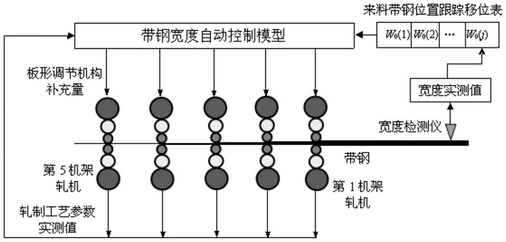
[0067] figure 1 In this technical scheme, a strip width detector is installed at the entrance of the cold tandem rolling mill to detect in real time the measured width values ​​at various positions in the length direction of the hot-rolled incoming material strip at the entrance of the cold-rolled mill, and calculate the actual measured value and the width of the hot-rolled incoming material. The difference between the set values ​​is distributed to each rack according to a certain ratio, and the variation of incoming strip width that needs to be eliminated by each rack is obtained.

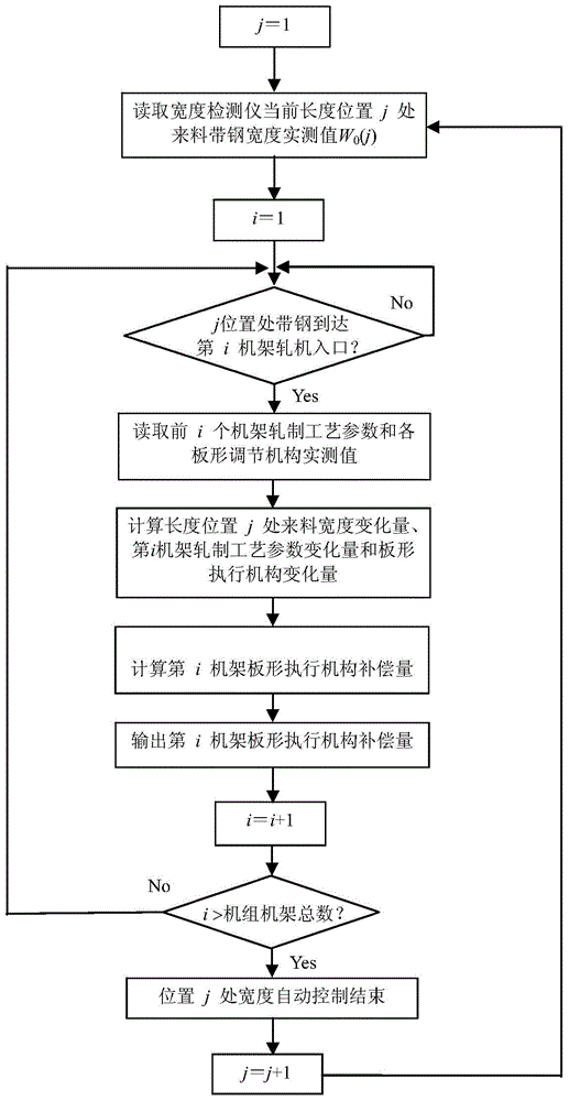
[0068] figure 2 In this technical solution, after establishing the strip width prediction model at the outlet of each rack, set the parameter j to 1, and then read the actual measured value W of the incoming strip width at the current length position j of the width detec...


PUM


Abstract

The invention relates to an automatic control method for width of steel strips during cold rolling, and belongs to the technical field of automatic control. The method includes: establishing forecasting models for width of exit steel strips for each stand; detecting width measured value at each position in the longitudinal direction of hot-rolled steel strips from an entry of a cold rolling unit in real time; calculating the differences between the measured values and preset values of width of the hot-rolled steel strips, and obtaining width variation of the hot-rolled steel strips to be eliminated by each stand; performing length position tracking on the hot-rolled steel strips from the entry of the cold rolling unit to obtain predicted values of exit width variation of the unit; determining real-time compensation of plate-shaped regulating mechanism of the No. m stand by changing compensation value of the plate-shaped regulating mechanism of a rolling mill of the stand in real time; according to the real time compensation of the plate-shaped regulating mechanism of each stand, performing feedforward control for exit width of each stand, and timely eliminating fluctuation of the width of the hot-rolled steel strips and influence on width of exit steel strips at the last stand by rolling technology parameter variation of each stand to improve width control precision of cold-rolled steel strips and stability of cold-rolling production process.

Description

technical field [0001] The invention belongs to the technical field of automatic control, and in particular relates to a method for automatic control of strip width in cold rolling, especially cold continuous rolling. Background technique [0002] It can be known from the theory and practice of strip rolling that the width of the strip will change during the cold rolling process due to the different degrees of widthwise flow of the metal in the strip in the load gap of the rolling mill. The difference between the width before and after rolling is usually called width reduction. During the strip cold rolling process, the change in width is mainly due to the change in the distribution of rolling force and tension in the width direction, which causes the change in the lateral flow direction of the metal at the end of the strip width, thereby changing the strip width. When the reduction of the edge of the strip is relatively large, that is, when the shape of the strip shows edg...

Claims


Application Information

Patent Timeline
Patent Type & Authority Patents(China)
IPC IPC(8): B21B37/22
CPCB21B37/22
Inventor 顾廷权樊志强刘云峰严加根
Owner BAOSHAN IRON & STEEL CO LTD
Why Eureka
Try Eureka