Method of forming thin-wall blank step by step with multi-rod force application

A billet and thin-walled technology, applied in the field of gradual forming of thin-walled billets, can solve the problems of uncontrollable large-size thin-walled billets, thinning or wrinkling, forming deformation, etc., and achieve simple structure, improved uniformity, and stress-bearing state reasonable effect

Active Publication Date: 2015-09-30
HARBIN INST OF TECH
View PDF4 Cites 1 Cited by
  • Summary
  • Abstract
  • Description
  • Claims
  • Application Information

AI Technical Summary

Problems solved by technology

[0004] The present invention aims to solve the problem that the existing forming methods and devices cannot effectively control the various parts when forming large-size thin-walled blanks, resulting in local deformation, thinning or wrinkling during forming. Force-based step-by-step forming method for thin-walled blanks

Method used


Image

  • Method of forming thin-wall blank step by step with multi-rod force application
  • Method of forming thin-wall blank step by step with multi-rod force application
  • Method of forming thin-wall blank step by step with multi-rod force application

Examples


specific Embodiment approach 1

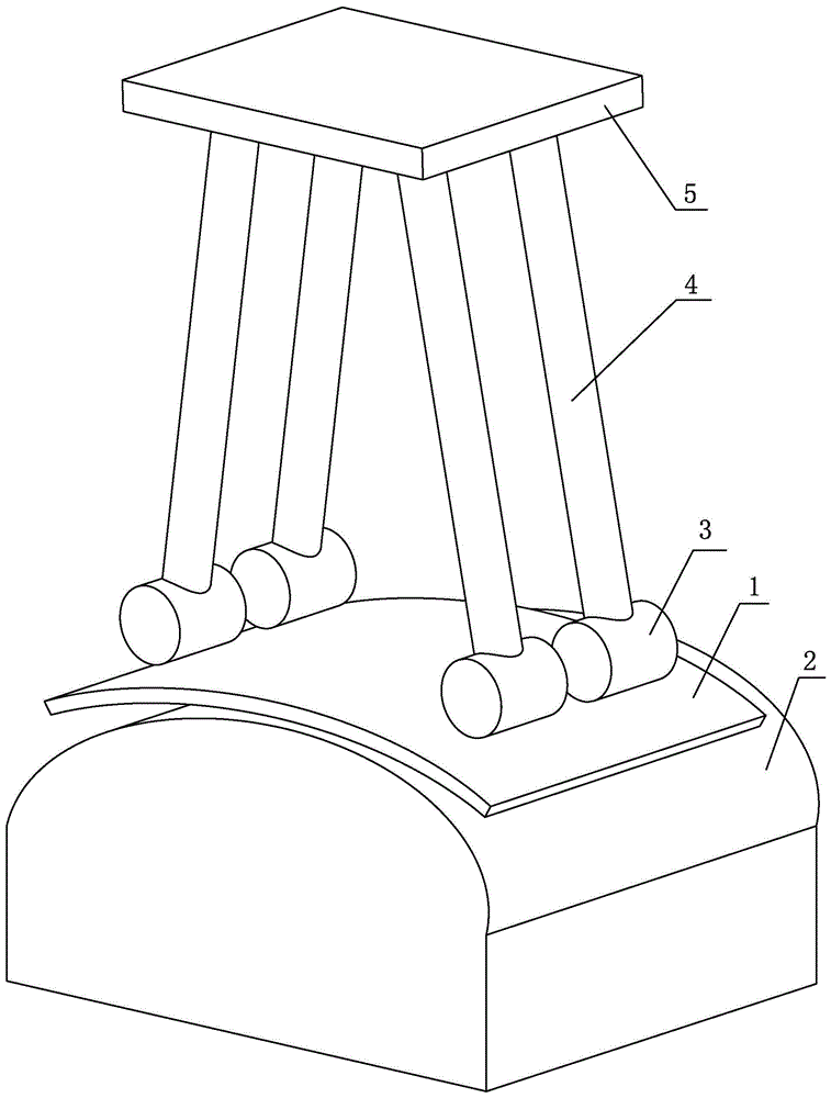
[0025] Specific implementation mode one: combine Figure 1-10 Explain that a step-by-step forming method for thin-walled blanks with multi-rod application of force in this embodiment is realized according to the following steps:

[0026] Step 1. Place the blank 1 that has been cut to be formed on the forming mold 2, and position and fix the blank 1;

[0027] Step 2, the force application platform 5 moves towards the forming mold 2 under the action of the press; wherein, the lower end surface of the force application platform 5 is rotatably connected with a plurality of force application rods 4;

[0028] Step 3, each connected forming head 3 on the plurality of force application rods 4 is in sliding contact with the blank 1, and at the same time, each reaction force element connected between the force application platform 5 and the plurality of force application rods 4 corresponds to the corresponding force application The rod 4 exerts a counter force, so that the forming head...

specific Embodiment approach 2

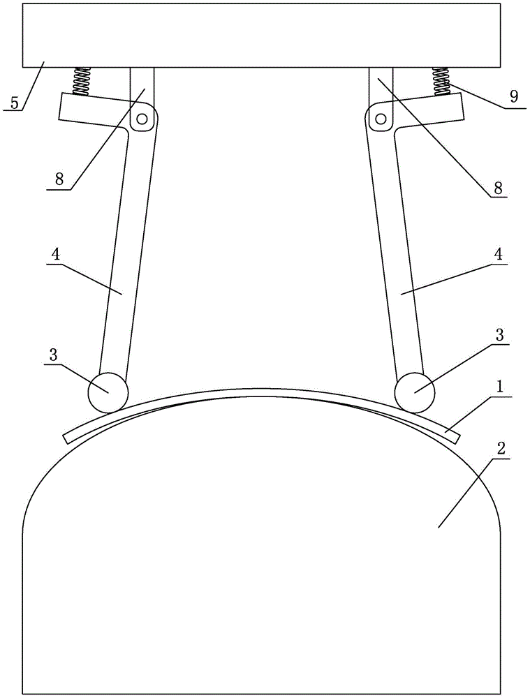
[0032] Specific implementation mode two: combination figure 1 and figure 2 Explain that the reaction force element in the step 3 of the present embodiment is a spring 9, and a plurality of force application rods 4 are curved rods, and the force application rods 4 are rotatably connected to the support rod 8 fixedly connected with the force application platform 5, and the force application The bend of the rod 4 can rotate around the support rod 8, one end of the spring 9 is connected with the force application platform 5, the other end of the spring 9 is connected with one end of the force application rod 4, the other end of the force application rod 4 is connected with the forming head 3, and the spring When 9 is compressed, a reaction force is generated to act on the force application rod 4, so that the forming head 3 connected with the force application rod 4 generates a force acting on the blank 1 to realize the deformation of the blank 1.

[0033] When the spring 9 of th...

specific Embodiment approach 3

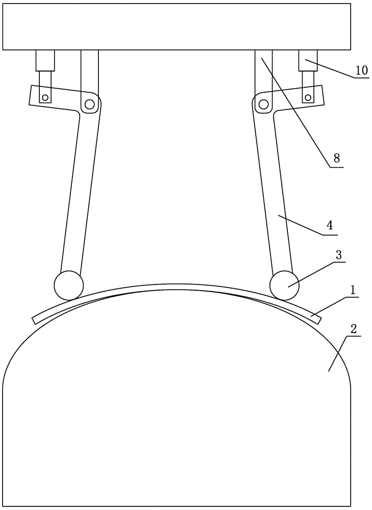
[0034] Specific implementation mode three: combination figure 1 and image 3 Explain that the reaction force element in step 3 of this embodiment is an oil cylinder 10, and a plurality of force application rods 4 are curved rods. The bend of the rod 4 can rotate around the support rod 8, the oil cylinder 10 is fixed on the lower surface of the force application platform 5, the driving rod of the oil cylinder 10 is connected with one end of the force application rod 4, and the other end of the force application rod 4 is connected with the forming head 3, When the oil cylinder 10 is compressed, a reaction force is generated to act on the force applying rod 4 , so that the forming head 3 connected with the force applying rod 4 generates a force acting on the blank 1 to realize the deformation of the blank 1 .

[0035] When the oil cylinder 10 of the present embodiment is compressed, a reaction force acts on the force application rod 4. The force application rod 4 is connected to...


PUM

PropertyMeasurementUnit
thicknessaaaaaaaaaa

Abstract

A method of forming a thin-wall blank step by step with multi-rod force application relates to a method of forming a thin-wall blank step by step, and solves the problem that the existing forming method and device cannot effectively control each part when a large-size thin-wall blank is formed, so that the local deformation, thinning or corrugation is caused during formation. The method comprises main steps: step one, the to-be-formed blank which is cut is placed on a forming mold, and the blank is positioned and fixed; step two, a force application platform moves to the forming mold under the effect of a press machine; step three, forming heads which are respectively connected with a plurality of force application rods are in sliding contact with the blank, and the forming heads which are connected with the force application rods generate force which acts on the blank, so that the blank deforms; step four, the force application platform continues approaching the forming mold under the effect of the press machine; and step five, after formation ends, the force application platform is removed, and the formed blank is taken down from the forming mold. The invention is used for the formation of the thin-wall blank.

Description

technical field [0001] The invention relates to a step-by-step forming method for a thin-walled blank, in particular to a step-by-step forming method for a thin-walled blank with force applied by multiple rods. Background technique [0002] In the aerospace and automotive fields, there are many large-sized sheet metal parts, which are large in one direction in the plane, up to 2m or even larger, and the thickness is generally in the range of 1-2mm, which is a typical thin-walled sheet metal part. . Such thin-walled sheet metal parts are generally formed from original sheet stock with equal wall thickness. Forming such thin-walled sheet metal parts can be carried out by stamping with a rigid die, that is, placing the blank in the mold, and using the relative movement of the upper and lower dies (or convex and concave dies) to force the blank to undergo plastic deformation to achieve a preset shape. During the forming process, the mold and the blank are only partially in con...

Claims


Application Information

Patent Timeline
Patent Type & Authority Applications(China)
IPC IPC(8): B21D22/02
CPCB21D22/02B21D37/10
Inventor 张坤林艳丽何祝斌苑世剑
Owner HARBIN INST OF TECH
Why Eureka
Try Eureka