Splicing device

A technology of splicing device and mounting seat, which is used in metal processing, metal processing equipment, forming tools, etc., can solve the problems of wrong splicing position, weak splicing, and defective products, so as to avoid module falling off, ensure assembly quality, and improve production. The effect of manufacturing efficiency

Inactive Publication Date: 2015-09-30
LIUZHOU WEIQI NUMERICAL CONTROL MACHINERY
View PDF4 Cites 0 Cited by
  • Summary
  • Abstract
  • Description
  • Claims
  • Application Information

AI Technical Summary

Problems solved by technology

However, because the connection between the two modules usually has a certain strength requirement, the clamping position will be relatively compact, and even the two modules are an interference fit, so a relatively large and stable force is required to complete the splicing, and manual methods are used. Splicing moulds, it is easy to cause the wrong splicing position, or the splicing is not firm enough to cause the module to fall off, or even cause the product to be defective

Method used


Image

  • Splicing device

Examples


Embodiment Construction

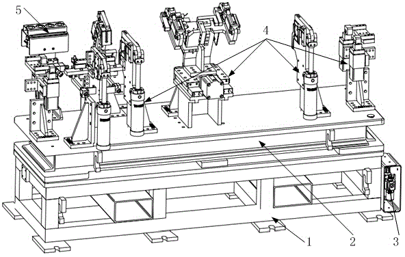
[0011] figure 1 The splicing device provided by the present invention is shown, and the splicing device includes a base 1, a mounting base 2, a cylinder control box 3, a second console, several brackets 4 and a first console 5, and the mounting base 2 is located on the On the base 1, several supports 4 are respectively arranged on the mounting base 2, the cylinder control box 3 is arranged on the side of the base 1, and the first console 5 is arranged on the side of the base, The output ends of the second console and the first console 5 are respectively connected to the input ends of the cylinder control box 3 . It can provide sufficient and stable stamping force during the assembly process of different modules, which can fully guarantee the assembly quality of the mold, effectively avoid the module falling off caused by weak splicing, realize the rapid assembly of the mold, and improve the manufacturing efficiency .

[0012] The base 1 is connected to the mounting base 2 by...


PUM


Abstract

The invention relates to a splicing device. The splicing device comprises a base, a mounting seat, an air cylinder control box, a second control platform, a plurality of supports and a first control platform, wherein the mounting seat is arranged on the base, the plurality of supports are arranged on the mounting seat respectively, the air cylinder control box is arranged on one side surface of the base, the first control platform is arranged on one side surface of the base, output ends of the second control platform and the first control platform are connected with an input end of the air cylinder control box respectively. The device can provide sufficient and stable stamping force during splicing of different modules, can sufficiently guarantee the splicing quality of molds, effectively avoids module falling-off caused by insecure splicing, realizes rapid splicing of the molds and improves production and manufacturing efficiency.

Description

technical field [0001] The invention relates to a splicing device for a girder assembly. Background technique [0002] In industrial production, some large-size plate forming processes must be completed with large-scale devices. In view of the large size of the board and the high difficulty of processing, it is generally made in the form of assembly. That is to say, several small modules are processed separately, and then assembled into large-sized equipment. [0003] In actual operation, the splicing between modules is usually done manually, that is, two modules are spliced ​​manually. However, because the connection between the two modules usually has a certain strength requirement, the clamping position will be relatively compact, and even the two modules are an interference fit, so a relatively large and stable force is required to complete the splicing, and manual methods are used. Splicing moulds, it is easy to cause wrong splicing position, or the splicing is not f...

Claims


Application Information

Patent Timeline
Patent Type & Authority Applications(China)
IPC IPC(8): B21D37/14B21D37/10
CPCB23P19/027
Inventor 曾耀宗蓝景钟周佳芬
Owner LIUZHOU WEIQI NUMERICAL CONTROL MACHINERY
Why Eureka
Try Eureka